A rain-shielding and defogging device for a rearview mirror of a vehicle

A technology of defogging device and rearview mirror, applied in optical observation devices, vehicle parts, vehicle maintenance, etc., can solve the problems of high energy consumption and affecting engine driving, etc.

Active Publication Date: 2022-06-21
JIANGSU UNIV
View PDF0 Cites 0 Cited by
  • Summary
  • Abstract
  • Description
  • Claims
  • Application Information

AI Technical Summary

Problems solved by technology

[0002] Traditional electrothermal rain removal devices consume a lot of energy during the rain removal process, which may affect the driving of the engine to the vehicle in severe cases

Method used


Image

  • A rain-shielding and defogging device for a rearview mirror of a vehicle
  • A rain-shielding and defogging device for a rearview mirror of a vehicle
  • A rain-shielding and defogging device for a rearview mirror of a vehicle

Examples


Embodiment 1

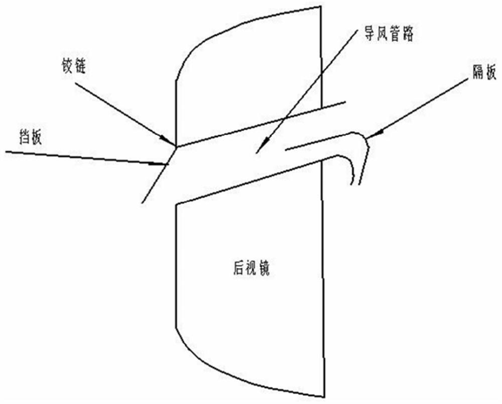
[0035] like figure 1 As shown in the figure, an air inlet with a larger cross-sectional area is arranged on the windward side of the rearview mirror, and a baffle is installed at the air inlet to ensure the flow rate of the inlet airflow. A hinged baffle is installed above or below the air inlet, so that the device can be opened or closed according to the needs of the driver.

[0036] The air guide pipe has a larger cross-sectional area at the air inlet and a smaller cross-sectional area at the air outlet, and its relative size is determined according to the required airflow speed:

[0037] Due to the characteristics of the external flow field of the vehicle, it can be considered as an incompressible ideal fluid model. From the fluid mass conservation equation, it can be known that v 1 A 1 ≈v 2 A 2 ;v 1 , A 1 are the inflow velocity of the air outlet and the cross-sectional area of ​​the air outlet, respectively, v 2 , A 2 are the outflow velocity of the air inlet and ...

Embodiment 2

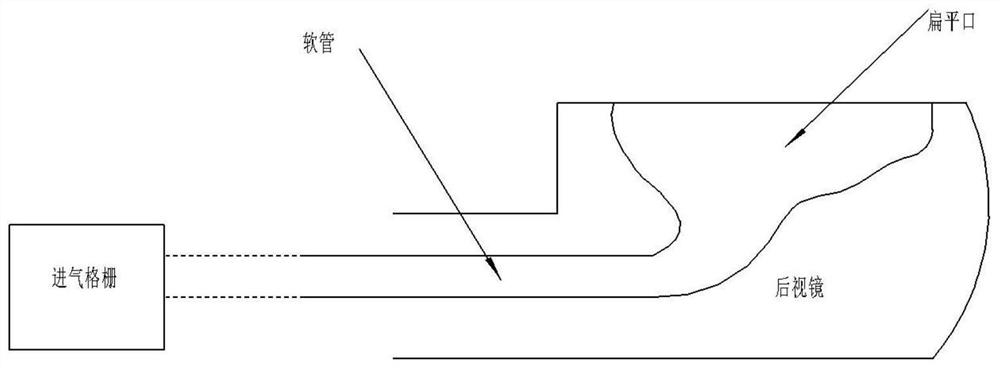
[0065] like figure 2 As shown in the figure, the air inlet is arranged at the rear of the mesh grille in front of the vehicle, and the air flow is introduced into the air outlet above the mirror through the side of the rearview mirror by a hose.

[0066] The air guide pipe has a larger cross-sectional area at the air inlet and a smaller cross-sectional area at the air outlet. The relative size can be determined by the following formula according to the required flow rate:

[0067] Due to the characteristics of the external flow field of the vehicle, it can be considered as an incompressible ideal fluid model. From the fluid mass conservation equation, it can be known that v 1 A 1 ≈v 2 A 2 v 1 , A 1 are the inflow velocity of the air outlet and the cross-sectional area of ​​the air outlet, respectively, v 2 , A 2 are the inlet air velocity and the air inlet cross-sectional area, respectively. The air guide pipe should use rounded corners to make smooth transitions at t...


PUM


Abstract

The invention discloses a rain-shielding and defogging device for a vehicle rearview mirror. When the vehicle is running at a certain speed, a high-speed airflow relative to the vehicle will be generated, and the air inlet is arranged in front of the rearview mirror or at the rear of the air intake grille at the front of the vehicle. The high-speed airflow entering from the air inlet is compressed through a specific duct and guided to the position above the mirror surface of the exterior rearview mirror. Design a special air duct opening at this position, so that the airflow flowing vertically to the rear of the mirror surface and the airflow blowing to the mirror surface at a certain angle are formed above the mirror surface. The airflow flowing backward from the vertical mirror surface mainly prevents rainwater from reaching the rearview mirror surface. The airflow blowing to the mirror surface at a certain angle is mainly responsible for blowing away the water mist on the mirror surface.

Description

technical field [0001] The patent of the present invention relates to the technical field of rain and fog removal for rearview mirrors, in particular to a rain and fog removal device for vehicle rearview mirrors. Background technique [0002] The traditional electric rain removal device consumes a lot of energy in the process of rain removal, which may affect the driving of the vehicle by the engine in severe cases. The present invention utilizes the high-speed airflow and wind force during the running of the vehicle to block rain and remove fog, thereby achieving no energy consumption. [0003] The traditional rain eyebrow needs to be attached above the rearview mirror of the car, and does not have the function of defogging. SUMMARY OF THE INVENTION [0004] In order to overcome the above-mentioned deficiencies of the prior art, the present invention provides a vehicle rearview mirror rain shielding and defogging device. General principle: When the vehicle runs at a cer...

Claims


Application Information

Patent Timeline
Patent Type & Authority Patents(China)
IPC IPC(8): B60R1/06B60S1/54
CPCB60R1/0602B60S1/54
Inventor 马世典陈晨韩牟江浩斌崔义忠梁军陈龙徐健李傲雪王浩祥
Owner JIANGSU UNIV
Why Eureka
Try Eureka