
Display panel and display device

A display panel and display area technology, which is applied to static indicators, instruments, semiconductor devices, etc., can solve problems such as poor display quality and uneven brightness of the display panel, and achieve the effect of improving uneven brightness and improving display quality

Inactive Publication Date: 2017-07-28
WUHAN TIANMA MICRO ELECTRONICS CO LTD
View PDF6 Cites 80 Cited by
  • Summary
  • Abstract
  • Description
  • Claims
  • Application Information

AI Technical Summary

Problems solved by technology

[0004] In this case, when each gate drive circuit drives each scan line, the drive signals output by each gate drive circuit corresponding to two scan lines with different lengths are different, which leads to uneven brightness of the display panel, and the display poor quality

Method used


Image

  • Display panel and display device
  • Display panel and display device
  • Display panel and display device

Examples


Embodiment Construction

[0075] The present application will be described in further detail below through specific embodiments and in conjunction with the accompanying drawings.

[0076] It should be noted that the orientation words such as "up", "down", "left", and "right" described in the embodiments of the present application are described from the angles shown in the drawings, and should not be interpreted as limiting the implementation of the present application. Example limitations. Furthermore, in this context, it also needs to be understood that when it is mentioned that an element is formed "on" or "under" another element, it can not only be directly formed "on" or "under" another element, but also be formed "on" or "under" another element. An element may be formed "on" or "under" another element indirectly through intervening elements.

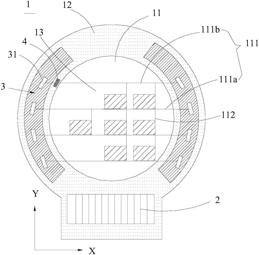
[0077] Please refer to figure 1 , which shows a schematic structural diagram of the display panel provided by the embodiment of the present application. ...


PUM


Abstract

The invention relates to a display panel and a display device. The display panel comprises a display zone and a non-display zone. The display zone comprises a plurality of scanning lines, and at least two scanning lines differ from each other in length. The non-display zone comprises a plurality of grating drive circuits and at least one load compensation unit wherein each grating drive circuit is connected with a scanning line respectively; each load compensation unit corresponds to a grating drive circuit to compensate the load of the grating drive circuit and the longer the scanning line in connection with the grating drive circuit is, the smaller the load is that corresponds to the load compensation unit. The display panel and the display device of the invention enable that the loads of various grating drive circuits in connection with scanning lines in different lengths tend to be consistent through the arrangement of the load compensation unit(s) so that the unevenness of display panel brightness is improved and the display quality of the display panel is increased.

Description

technical field [0001] The present application relates to the field of display technology, in particular to a display panel and a display device. Background technique [0002] The display panel includes a plurality of scanning lines and a plurality of data lines, the scanning lines and the data lines are intersected to define a plurality of pixel areas, and the plurality of pixel areas are arranged in an array. With the continuous innovation of display products, the application fields of display panels are becoming more and more extensive. Display panel manufacturers have begun to design and produce special-shaped display panels. of polygons. [0003] In the special-shaped display panel, since the number of pixels in at least two rows is different, correspondingly, the lengths of the scanning lines in at least the two rows are not equal, which makes the load of the gate driving circuit driving the scanning lines different, and the driving is relatively slow. The load of th...

Claims


Application Information

Patent Timeline
IPC IPC(8): G09G3/36G09G3/3208
CPCG09G3/3208G09G3/3677H10K59/12G09G2300/0426G09G2320/0223G09G3/2092G09G2320/0233G09G2300/0876G09G3/3266G09G2310/0213H01L27/1214G09G2300/0413G02F1/134309G02F1/13452G02F1/13454G09G3/3648G09G3/3674G02F1/133305H10K59/131
Inventor 李春阳向东旭李玥
Owner WUHAN TIANMA MICRO ELECTRONICS CO LTD
Learn More