
Laser machining clamp

A laser processing and fixture technology, applied in manufacturing tools, laser welding equipment, metal processing equipment, etc., can solve the problems of heat accumulation and dissipation speed, which have a great influence on the processing process, fast heat conduction, and poor clamping effect.

Active Publication Date: 2017-07-28
SUZHOU UNIV
View PDF7 Cites 17 Cited by
  • Summary
  • Abstract
  • Description
  • Claims
  • Application Information

AI Technical Summary

Problems solved by technology

[0004] However, based on the fact that laser processing is a rapid heating and cooling process, the speed of heat accumulation and dissipation has a great influence on the processing process.
The workpiece is directly placed on the rotary table, and the heat conduction is fast, which will affect the analysis of the actual distribution of laser heat on the steel plate. However, if the workpiece is placed on an ordinary vise, if the cutting surface of the steel plate is uneven, the clamping effect will not be good. Difficult to guarantee level
Furthermore, when carrying out cladding experiments on inclined surfaces in space, the vise is fixed on the rotary table, and the vise and the stainless steel plate can be rotated to a certain angle with the help of the rotation of the rotary table, but the angle cannot be accurately measured. Although the tiltable flat vise can rotate the stainless steel plate at a certain angle, its clamping part will also have the same problems as the ordinary vise

Method used


Image

  • Laser machining clamp
  • Laser machining clamp
  • Laser machining clamp

Examples


Embodiment Construction

[0032] Based on the fact that laser processing is a process of rapid heating and rapid cooling, the speed of heat accumulation and dissipation has a great influence on the processing process. The workpiece is directly placed on the rotary table, and the heat conduction is fast, which will affect the analysis of the actual distribution of laser heat on the steel plate. However, if the workpiece is placed on an ordinary vise, if the cutting surface of the steel plate is uneven, the clamping effect will not be good. It is not easy to guarantee the level. Furthermore, when carrying out cladding experiments on inclined surfaces in space, the vise is fixed on the rotary table, and the vise and the stainless steel plate can be rotated to a certain angle with the help of the rotation of the rotary table, but the angle cannot be accurately measured. Although the tiltable flat vise can rotate the stainless steel plate at a certain angle, the same problem as the ordinary vise will appear...


PUM


Abstract

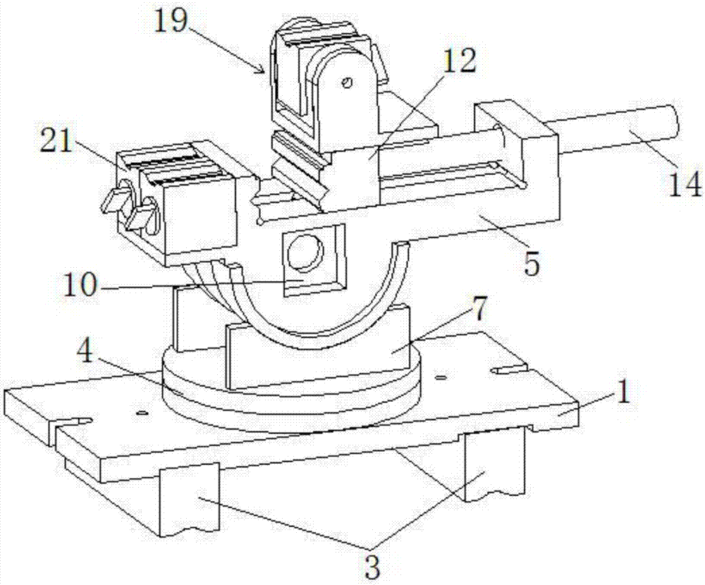
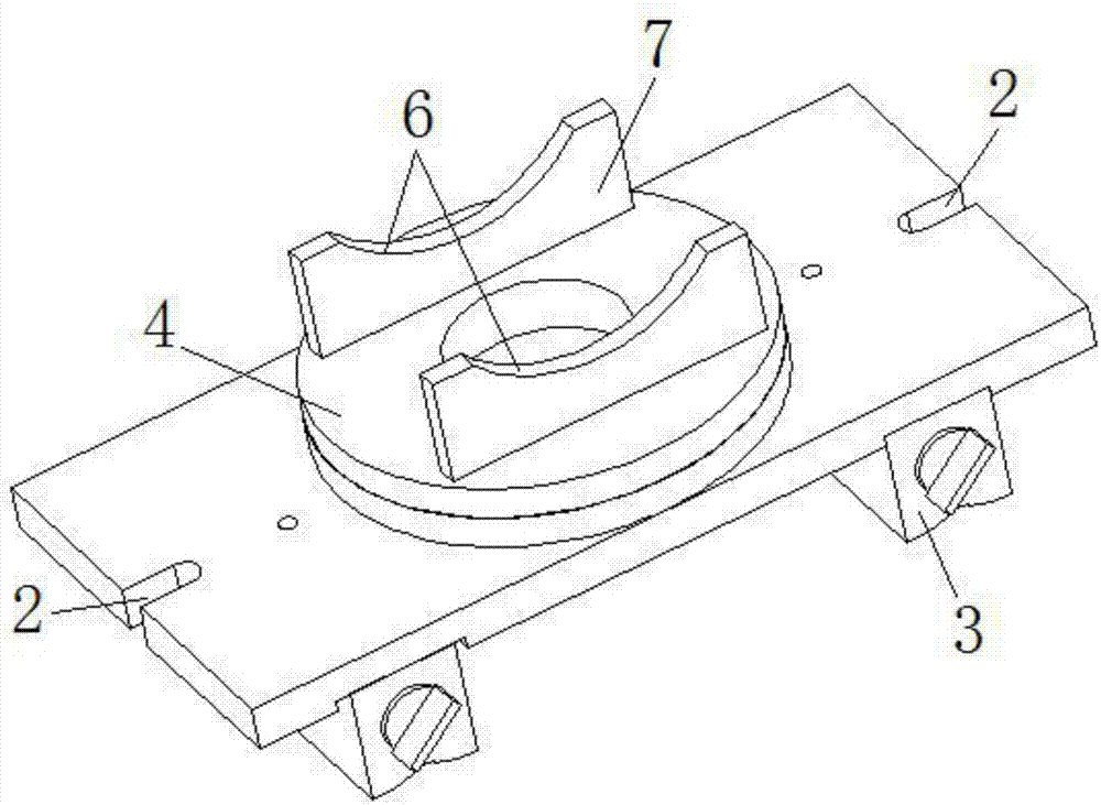
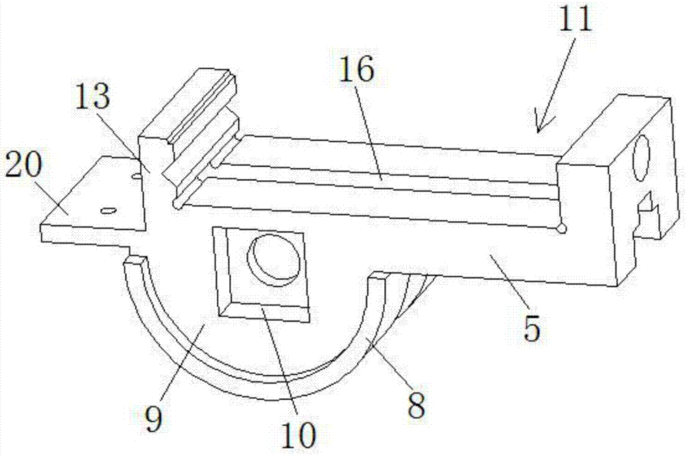
The invention discloses a laser machining clamp which comprises a base, a rotating unit and a clamping unit. The base is provided with a rotating platform capable of rotating in the axis direction of the base. A clamp body which can swing and rotate is arranged on the rotating platform. The rotating axis of the clamp body is perpendicular to the axis of the rotating platform. A rotating unit is composed of the rotating platform and the clamp body. A perpendicularly and inwards concave clamping groove is formed in the surface of the clamp body. A movable clamping piece which can slide in a reciprocating manner is arranged in the clamping groove in a matched manner. A clamping unit is composed of the movable clamping piece and one side of the clamping groove. A rotatable auxiliary clamp part is arranged on the top of the movable clamping piece. A clamp platform is arranged on one side of the clamping unit composed of the clamping groove, and a clamp part is arranged on the clamp platform. A clamp unit is composed of the top face of one side of the clamping unit composed of the auxiliary clamp part, the clamp part and the clamping groove. By means of the laser machining clamp, various machining requirements of thick plates in horizontal, perpendicular and oblique directions can be met.

Description

technical field [0001] The invention relates to the technical field of laser processing machinery, in particular to a fixture for laser processing. Background technique [0002] Laser processing is the fastest growing, most widely used, and most promising field of laser application technology. At present, more than 20 laser processing technologies have been developed, such as laser welding, laser cutting, laser rapid prototyping, Laser repair, etc., are widely used in machinery, electronics, automobiles and other industries. Compared with traditional mechanical processing methods, laser processing has incomparable advantages. Laser processing has high processing precision, fast speed, small mechanical deformation, material saving, It has the advantages of good flexibility and wide processing range. At the same time, laser processing is easy to combine with computer-aided design / computer-aided manufacturing, which is convenient for the control of the production process, and i...

Claims


Application Information

Patent Timeline
Patent Type & Authority Applications(China)
IPC IPC(8): B23K26/70B23K26/21B23K37/04B25B1/22B25B1/24B25B1/10
CPCB23K26/21B23K26/702B23K37/0452B25B1/10B25B1/22B25B1/2494
Inventor 鹿霖傅戈雁石世宏王敏伟
Owner SUZHOU UNIV
Learn More