Unmanned aerial vehicle motor base, unmanned aerial vehicle driving device and unmanned aerial vehicle

A driving device, electromechanical technology, applied in the field of drones, can solve problems such as drone vibration

Active Publication Date: 2017-07-25
昆山合朗航空科技有限公司
View PDF5 Cites 6 Cited by
  • Summary
  • Abstract
  • Description
  • Claims
  • Application Information

AI Technical Summary

Problems solved by technology

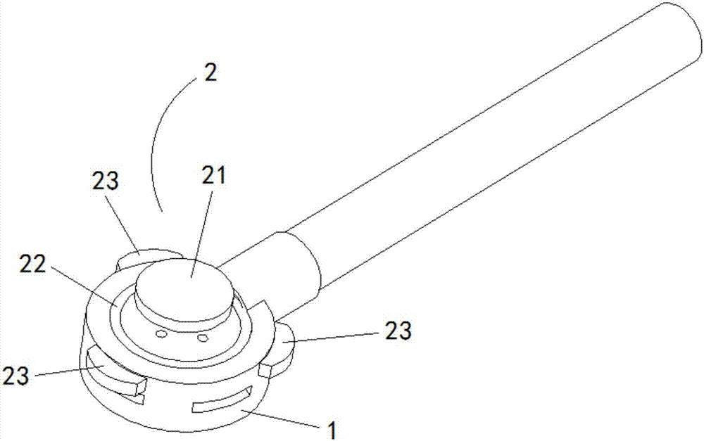
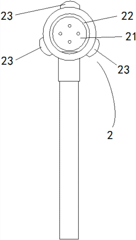
[0007] The purpose of the present invention is to provide a UAV motor base, UAV driving device and UAV, to solve the problem that the hard-connected connection mode in the prior art will transmit the vibration generated by the motor to the fuselage, so that no The technical problem of the violent vibration of the man-machine

Method used


Image

  • Unmanned aerial vehicle motor base, unmanned aerial vehicle driving device and unmanned aerial vehicle
  • Unmanned aerial vehicle motor base, unmanned aerial vehicle driving device and unmanned aerial vehicle
  • Unmanned aerial vehicle motor base, unmanned aerial vehicle driving device and unmanned aerial vehicle

Examples


Embodiment Construction

[0046] The technical solutions of the present invention will be clearly and completely described below in conjunction with the accompanying drawings. Apparently, the described embodiments are some of the embodiments of the present invention, but not all of them. Based on the embodiments of the present invention, all other embodiments obtained by persons of ordinary skill in the art without making creative efforts belong to the protection scope of the present invention.

[0047] In the description of the present invention, it should be noted that the terms "center", "upper", "lower", "left", "right", "vertical", "horizontal", "inner", "outer" etc. The indicated orientation or positional relationship is based on the orientation or positional relationship shown in the drawings, and is only for the convenience of describing the present invention and simplifying the description, rather than indicating or implying that the referred device or element must have a specific orientation, ...


PUM


Abstract

The invention provides an unmanned aerial vehicle motor base, an unmanned aerial vehicle driving device and an unmanned aerial vehicle. The unmanned aerial vehicle motor base comprises a motor base body, and further comprises a magnetic suspension damping mechanism. The magnetic suspension damping mechanism comprises a permanent magnet, an electromagnetic coil and at least one hall sensor. The permanent magnet is used for being connected with a motor. The electromagnetic coil and the hall sensors are located in the motor base body. The hall sensors correspond to the permanent magnet and are used for generating an electric signal for adjusting the magnetism of the electromagnetic coil according to variation of a magnetic field of the permanent magnet. According to the technical scheme, the magnetism of the electromagnetic coil can be adjusted according to the electric signal, the magnetism varies as displacement of the permanent magnet varies, the effect of mutual repelling or attracting between the electromagnetic coil and the permanent magnet due to identical or different magnetisms is achieved, and vibration of the motor is relieved in a magnetic suspension mode before being transmitted to a fuselage.

Description

technical field [0001] The invention relates to the technical field of unmanned aerial vehicles, in particular to an unmanned aerial vehicle motor base, an unmanned aerial vehicle driving device and an unmanned aerial vehicle. Background technique [0002] Unmanned aircraft, referred to as "UAV", is an unmanned aircraft controlled by radio remote control equipment and its own program control device. [0003] There is no cockpit on the fuselage of the UAV, but equipment such as autopilot and program control device are installed. The personnel on the ground, on the ship, or at the remote control station of the parent aircraft track, locate, remotely control, telemeter and digitally transmit it through radar and other equipment. [0004] The UAV can take off like an ordinary aircraft under radio control or be launched into the air with a booster rocket, or it can be brought into the air by the parent aircraft for flight. When recovering, it can automatically land in the same ...

Claims


Application Information

Patent Timeline
IPC IPC(8): B64C27/14B64D27/26
CPCB64C27/14B64U50/19B64D27/40
Inventor 田瑜江文彦王培乐
Owner 昆山合朗航空科技有限公司
Why Eureka
Try Eureka