
Metro environment control system and method

A technology for control systems and subways, applied in air-conditioning systems, heating methods, lighting and heating equipment, etc., can solve the problems of huge difference in energy-saving effects, difficulty in using subway piston wind, etc., and achieve low cost, reduced energy consumption, and simplified air-conditioning systems Effect

Active Publication Date: 2019-11-22
南通誉力智能装备有限公司
View PDF5 Cites 0 Cited by
  • Summary
  • Abstract
  • Description
  • Claims
  • Application Information

AI Technical Summary

Problems solved by technology

It can be seen that due to the heating problem in the subway track area, it is difficult to effectively use the subway piston wind in the air-conditioning season, resulting in a huge difference in energy-saving effect between the air-conditioning season and the non-air-conditioning season

Method used


Image

  • Metro environment control system and method
  • Metro environment control system and method
  • Metro environment control system and method

Examples


Embodiment 1

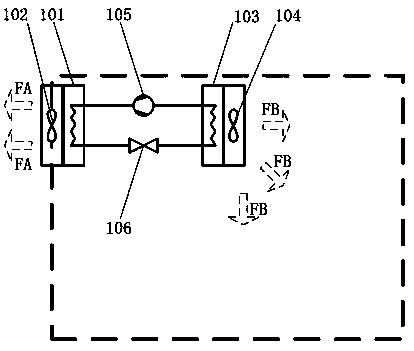
[0048] Existing subway train air-conditioning systems are usually set on the top of the carriage (such as figure 1shown), including condenser 101, condensing fan 102, evaporator 103, blower 104, compressor 105, throttle valve 106, compressor 105→condenser 102→throttle valve 106→evaporator 103 forms a refrigeration cycle, where The condenser 101 is used in conjunction with the condensing fan 102 to discharge heat to the outer space of the train through the condensing fan 102; the evaporator 103 is used in conjunction with the blower 104 to blow cold air to the inner space of the train through the blower 104.

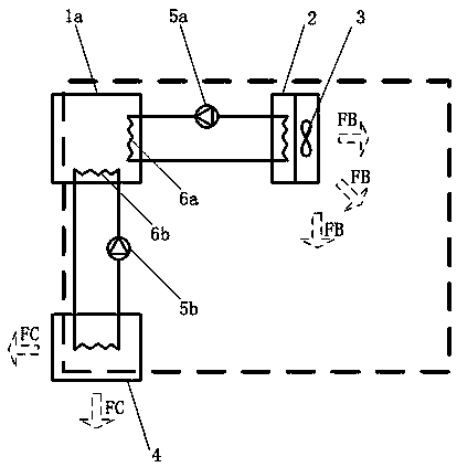
[0049] Compared with the existing subway train air-conditioning system, the main difference between the subway train interior air-conditioning system of the present invention is that the present invention simplifies the structure of the air-conditioning host. Firstly, the condenser 101, condensing fan 102, compressor 105, throttle valve 106 and other parts are canceled, r...

Embodiment 2

[0064] This embodiment specifically introduces the setting and operation mode of the cold storage system of the present invention.

[0065] Such as Image 6 As shown, when the mobile cold storage module is used, the replacement process of the cold storage module takes a long time, so the cold storage system of the starting station and the cold storage system of the terminal station are respectively installed at the starting station and the terminal station of the subway line. The specific operation mode is:

[0066] The cold storage system of the starting station and the cold storage system of the terminal station store the offline cold storage modules separately, and run the cooling mode to supplement the cooling capacity of the offline cold storage modules in the system, usually during the night valley power period;

[0067] When the subway train arrives at the starting station, unload the on-board (online) cold storage module that has released the cooling capacity and put ...


PUM


Abstract

A subway environment control system is characterized in that the system at least comprises a cool storage module (1) and a subway train air-conditioning system. A cool storage working medium is stored in the cool storage module (1). In the running process of a subway train (8), the cool storage module (1) serves as a cold source of the subway train air-conditioning system to release the cold quantity through the subway train air-conditioning system. Through the combined technical scheme of a cool storage system and the subway train, heat discharging is reduced or counteracted in the running process of the subway train, so that a heat-extraction system in a station rail traveling area is simplified or cancelled, energy consumption is reduced, and long period running of a subway system is facilitated.

Description

technical field [0001] The invention relates to a subway environment control system and method, in particular to a technical solution combining a cold storage system with a subway train to reduce or offset the heat discharge during the operation of the subway train, thereby simplifying or canceling the heat dissipation in the track area of ​​the station system, reduce energy consumption, and be beneficial to the long-term operation of the subway system, and belong to the technical field of the design and manufacture of the subway environment control system. Background technique [0002] In the existing subway environment control system, a station track area heat removal system is set up to solve the problem of heating in the subway track area. Its purpose is to discharge the local heat dissipation of the train’s air-conditioning condenser and brakes in time when the train stops, so as to ensure the normal operation of the air-conditioning condenser on the top of the train an...

Claims


Application Information

Patent Timeline
Patent Type & Authority Patents(China)
IPC IPC(8): F24F5/00
CPCF24F5/0017F24F2005/0032Y02B10/40Y02E60/14
Inventor 朱杰
Owner 南通誉力智能装备有限公司
Learn More