
A new type of air purification equipment

An air purification equipment and a new type of technology, applied in the field of air purification, can solve the problems of easy arc generation, damage, poor plug stability, etc., and achieve the effect of improving work efficiency, improving operation stability and reducing personnel workload.

Active Publication Date: 2018-07-10
JIANGSU XIYI HIGH NEW DISTRICT TECH DEV CO LTD
View PDF7 Cites 0 Cited by
  • Summary
  • Abstract
  • Description
  • Claims
  • Application Information

AI Technical Summary

Problems solved by technology

[0002] The fresh air fan is an effective air purification equipment that can circulate the indoor air. On the one hand, the indoor dirty air is discharged outside, and on the other hand, the fresh outdoor air is sterilized, disinfected, filtered and other measures, and then input into the room. , so that the room is full of fresh and clean air all the time. The fresh air fan uses the fresh air convection technology to achieve convection of the indoor air through independent air supply and induction, so as to maximize the indoor air replacement and ensure that it enters the room. The air is clean and healthy. However, due to the high voltage required in the working process of the fresh air blower, through the existing manual plugging power supply mode, the plugging stability is poor, and arcs are likely to be generated during the plugging process. The generation of arcs is likely to cause users The electric shock has a certain potential danger to the user, which will cause safety accidents and cause casualties. Moreover, when the power supply is plugged in, there is no protection device, and it is easy to loosen or cause damage to the plug connector due to accidental touch by personnel. There are major disadvantages. meet existing needs

Method used


Image

  • A new type of air purification equipment
  • A new type of air purification equipment
  • A new type of air purification equipment

Examples


Embodiment Construction

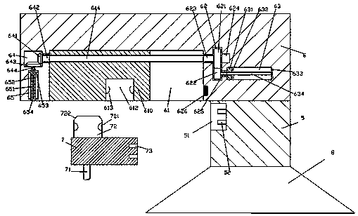
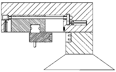
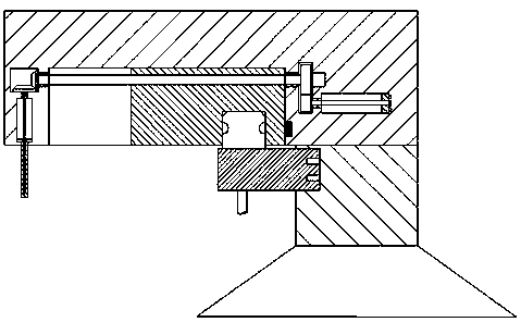
[0024] like Figure 1-Figure 5 As shown, a new type of air purification equipment of the present invention includes a base 8, a body 5 fixed above the base 8, a frame body 6 fixed on the top of the body 5 and extending to the left, and a frame connected to the frame The body 6 is matched with the electrical joint head 7 connected, and the left end surface of the body 5 is provided with a fastening groove 51, and the inner wall of the right side of the fastening groove 51 is provided with a second latch 52, and the left side of the frame body 6 is extended. The bottom end face is provided with a sliding groove 61, and the sliding groove 61 is provided with a first stud 614 extending left and right, and the first stud 614 is threadedly connected with a push block 610, and the sliding groove The frame body 6 on the left side of 61 is provided with a first transfer cavity 64, the frame body 6 below the first transfer cavity 64 is provided with a first sliding cavity 65, and the fr...


PUM


Abstract

The invention discloses novel air purifying equipment comprising a base, a machine body fixed on the base, a frame body fixed on the top of the machine body and extending toward the left side and an electric linking head connected with the frame body in a matched mode. A tightly-plugging groove is formed in the end face of the left side of the machine body. Second plug pins are arranged on the inner wall of the right side of the tightly-plugging groove. A slidably-pushing groove is formed in the end face of the bottom at the extending section of the left side of the frame body. A first stud extending leftward and rightward is arranged in the slidably-pushing groove. A pushing block is connected on the first stud in a thread fit mode. A first conveying cavity is formed in the interior, on the left side of the slidably-pushing groove, of the frame body. A first sliding cavity is formed in the interior, below the first conveying cavity, of the frame body. A second conveying cavity is formed in the interior, on the right side of the slidably-pushing groove, of the frame body. A first steering shaft extending leftward and rightward is arranged in the second conveying cavity. The right side end of the first steering shaft is connected with a motor. The structure is simple; plugging connection can be automatically controlled; power supply connection and spacing block stretching are automatically controlled; the working efficiency is high; and safety is high.

Description

technical field [0001] The invention relates to the technical field of air purification, in particular to a novel air purification equipment. Background technique [0002] The fresh air fan is an effective air purification equipment that can circulate the indoor air. On the one hand, the indoor dirty air is discharged outside, and on the other hand, the fresh outdoor air is sterilized, disinfected, filtered and other measures, and then input into the room. , so that the room is full of fresh and clean air all the time. The fresh air fan uses the fresh air convection technology to achieve convection of the indoor air through independent air supply and induction, so as to maximize the indoor air replacement and ensure that it enters the room. The air is clean and healthy. However, due to the high voltage required in the working process of the fresh air blower, through the existing manual plugging power supply mode, the plugging stability is poor, and arcs are likely to be gene...

Claims


Application Information

Patent Timeline
Patent Type & Authority Patents(China)
IPC IPC(8): F24F1/00F24F3/16F24F13/00H01R13/631H01R13/627
CPCF24F3/16F24F13/00H01R13/6278H01R13/631
Inventor 潘王琴
Owner JIANGSU XIYI HIGH NEW DISTRICT TECH DEV CO LTD
Learn More