Double-cylinder braking master cylinder system provided with pedal sensing simulator

A brake master cylinder and simulator technology, applied in the directions of brake, brake transmission, transportation and packaging, can solve the problems of large pressure fluctuation of the master cylinder, large workload, not direct enough, etc., to improve the smoothness, Improve the effect of driving experience

Pending Publication Date: 2017-07-21
潘泓冰
View PDF0 Cites 0 Cited by
  • Summary
  • Abstract
  • Description
  • Claims
  • Application Information

AI Technical Summary

Problems solved by technology

[0004] In order to solve the problem that the structure of the existing vehicle brake-by-wire master cylinder is complex and the cost is relatively high, and when the pressure is actively built, the pressure of the master cylinder fluctuates greatly due to reasons such as valve accuracy and control accuracy, which in turn leads to relatively large fluctuations in the braking force. It is a big problem, and the existing pedal simulators generally use the spring plus piston type to simulate the braking force through the spring force feedback, which is not direct enough; because the force-displacement curve of the brake is nonlinear, and different vehicles, the force- Displacement curves are also different, so different spring parameters need to be designed, the workload is large, and the cost is high. The invention provides a dual-cylinder brake master cylinder system with a pedal feel simulator. The system improves the master cylinder The pressure control accuracy reduces the pressure fluctuation of the brake master cylinder during active boosting, reduces the fluctuation of the braking force, makes the braking force smoother, and improves the user's driving experience; the hydraulic direct-feeding pedal feeling simulator is adopted, and the original simulator has been removed. The spring directly feeds back the pedal braking force through the hydraulic pressure, and at the same time, it only needs to choose different push rod diameters to feedback different pedal feel

Method used


Image

  • Double-cylinder braking master cylinder system provided with pedal sensing simulator
  • Double-cylinder braking master cylinder system provided with pedal sensing simulator
  • Double-cylinder braking master cylinder system provided with pedal sensing simulator

Examples


Embodiment

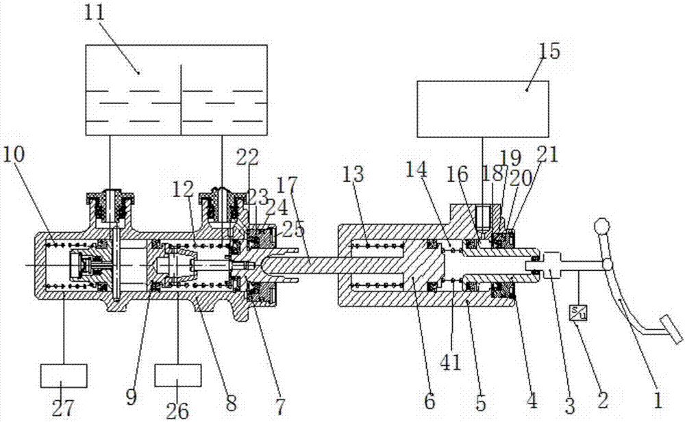
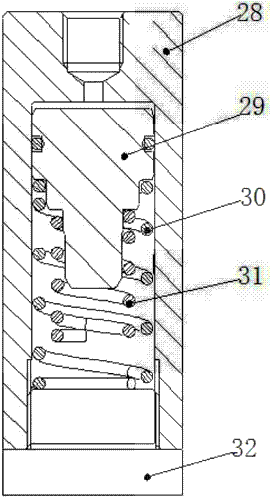
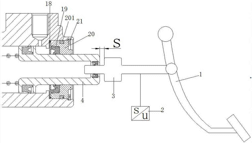
[0041] Such as figure 1 , 2 , 3 shown, which attached figure 2 It is a structural schematic diagram of an existing pedal feel simulator; the invention provides a dual-cylinder brake master cylinder system with a pedal feel simulator; the system includes: a brake pedal 1, a push rod 3, a booster cylinder block 5. Conventional master cylinder body 8, booster system 15 and oil pot 11; booster cylinder body 5 is provided with T-shaped piston 4 and first piston 6, push rod one 3 is connected with T-shaped piston 4, T-shaped Form booster cylinder main chamber 14 between piston 4 and the first piston 6; Be provided with baffle plate one 18 between T shape piston 4 and booster cylinder body 5, baffle plate one and T shape head of T shape piston and booster A booster cylinder boost chamber 16 is formed between the cylinder walls, and the booster cylinder booster chamber 16 is connected to the booster system 15; the conventional master cylinder body 8 is provided with a second pisto...


PUM


Abstract

The invention relates to a double-cylinder sensing master cylinder system provided with a pedal sensing simulator. The system comprises a braking pedal, a first push rod, a booster cylinder block, a regular master cylinder block, a booster system and an oiler. A T-shaped piston and a first piston are arranged in the booster cylinder block. The first push rod is connected with the T-shaped piston. A booster cylinder cavity is formed between the T-shaped piston and the first piston. A first baffle is arranged between the T-shaped piston and the booster cylinder block. A booster cylinder booster cavity is formed among the first baffle, a T-shaped head of the T-shaped piston and the wall of a booster cylinder, and is connected with a supercharging system. A second piston and a third piston are arranged in the regular master cylinder block. A second push rod is arranged on the first piston and penetrates through the booster cylinder block to be connected with the second piston. The effective cross sectional area of the T-shaped piston is smaller than that of the first piston. By adoption of the system, the control precision for pressure of the master cylinder is improved, and pressure fluctuation of the braking master cylinder during active supercharging is reduced.

Description

technical field [0001] The invention relates to a vehicle brake system, in particular to a dual-cylinder brake master cylinder system with a pedal feeling simulator. Background technique [0002] At present, the structure of the brake-by-wire master cylinder system is complex and the cost is high; and when the pressure is actively built, due to the valve accuracy and control accuracy, the pressure of the master cylinder fluctuates greatly, which in turn causes the braking force to fluctuate greatly, which seriously affects the user driving experience. [0003] Pedal simulators generally use a spring plus piston type, and the braking force is simulated through spring force feedback, which is not direct enough. Since the force-displacement curve of the brake is nonlinear, and different vehicles have different force-displacement curves, it is necessary to design different spring parameters, which requires a lot of work and high cost. Contents of the invention [0004] In or...

Claims


Application Information

Patent Timeline
Patent Type & Authority Applications(China)
IPC IPC(8): B60T13/12B60T8/40
CPCB60T8/409B60T13/145
Inventor 潘泓冰
Owner 潘泓冰
Why Eureka
Try Eureka