Combination Control Method Based on Object Image Feature Point Pixel Spatial Position
A technology of spatial position and combined control, applied in image analysis, image data processing, program-controlled manipulators, etc., can solve the problems of low control information accuracy, divergence of action errors, and accuracy loss of lock, etc., to improve the ability of self-compensation adjustment and compensation. The effect of adjusting accuracy, suppressing action errors, and improving reliability
- Summary
- Abstract
- Description
- Claims
- Application Information
AI Technical Summary
Problems solved by technology
Method used
Image
Examples
Embodiment 1
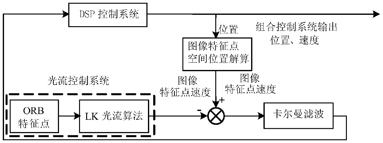
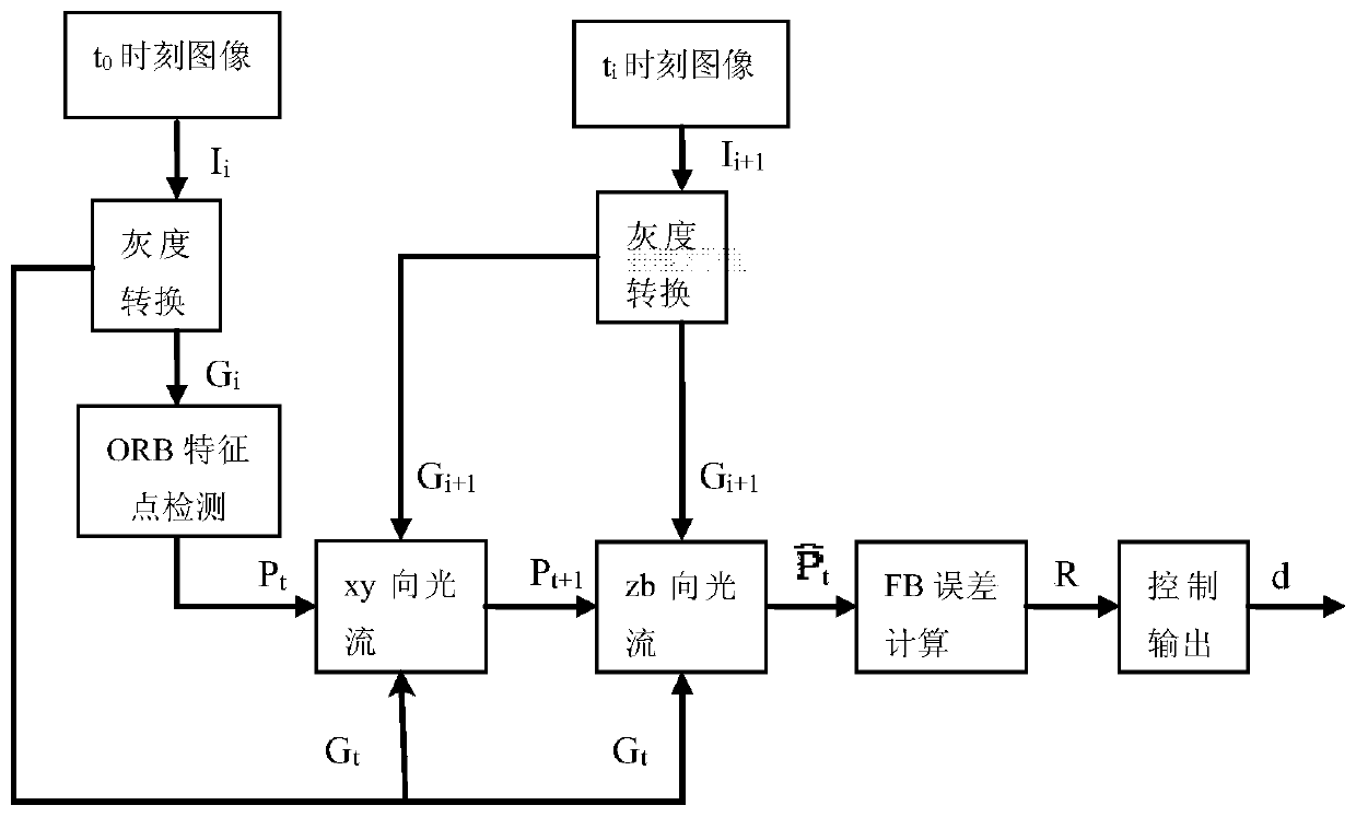
[0031] Example one. Combination control method based on the pixel spatial position of the feature point of the object image, such as figure 1 As shown, including the following steps:
[0032] a. Install a 2D vision system camera so that the x-axis, y-axis, and z-axis of the coordinate system of the 2D vision system camera coincide with the front, back, left, and right, up and down coordinate axes of the robot system;
[0033] b. Use the 2D vision system camera to collect the image of the object features captured by the robot's end axis. 0 The image collected at any moment is I 0 , In T n The image collected at any moment is I n ;
[0034] c. Use ORB feature point detection method to detect I 0 The coordinate set of the feature point in P 0 ;
[0035] d, I 0 , P 0 , I n As the input, I get I through the LK optical flow pyramid method 0 The characteristic points in I n Set of coordinates in
[0036] e, I n , I 0 As the input, the feature point set P is obtained by the LK optical flow ...
Embodiment 2
[0052] Example two. Combination control method based on the pixel spatial position of the feature point of the object image, such as figure 1 As shown, including the following steps:
[0053] a. Install a 2D vision system camera so that the x-axis, y-axis, and z-axis of the coordinate system of the 2D vision system camera coincide with the front, back, left, and right, up and down coordinate axes of the robot system;
[0054] b. Use the 2D vision system camera to collect the image of the object features captured by the robot's end axis. 0 The image collected at the moment is I 0 , In T n The image collected at any moment is I n ;
[0055] c. Use ORB feature point detection method to detect I 0 The coordinate set of the feature point in P 0 ;
[0056] d, I 0 , P 0 , I n As the input, I get I through the LK optical flow pyramid method 0 The characteristic points in I n Set of coordinates in
[0057] e, I n , I 0 As the input, the feature point set P is obtained by the LK optical flow ...
PUM
 Abstract
Description
Claims
Application Information
 - R&D
- Intellectual Property
- Life Sciences
- Materials
- Tech Scout
- Unparalleled Data Quality
- Higher Quality Content
- 60% Fewer Hallucinations
Browse by: Latest US Patents, China's latest patents, Technical Efficacy Thesaurus, Application Domain, Technology Topic, Popular Technical Reports.
© 2025 PatSnap. All rights reserved.Legal|Privacy policy|Modern Slavery Act Transparency Statement|Sitemap|About US| Contact US: help@patsnap.com


