
Multi-task ion determination device

A measurement device and multi-task technology, applied in the field of chemical determination, can solve the problems of low efficiency during measurement, achieve the effects of saving electric energy, avoiding unclean cleaning and prolonging the service life

Pending Publication Date: 2017-07-18
湖州市环境保护监测中心站
View PDF7 Cites 1 Cited by
  • Summary
  • Abstract
  • Description
  • Claims
  • Application Information

AI Technical Summary

Problems solved by technology

[0003] The purpose of the present invention is to provide a multi-task ion measurement device, so that when the ion meter is used to measure sample data, the measurement process can be carried out simultaneously and multi-task, and the stable judgment and reading record of the real-time measurement data can be automatically performed by the workstation software , to solve the problem of low efficiency in traditional measurement

Method used


Image

  • Multi-task ion determination device
  • Multi-task ion determination device
  • Multi-task ion determination device

Examples


Embodiment 1

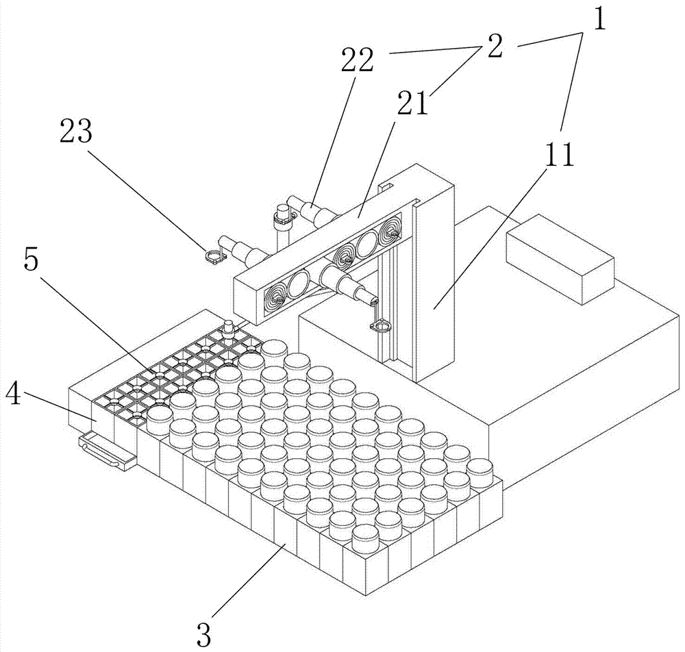
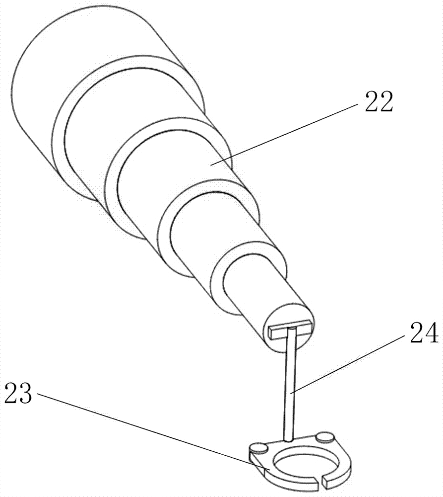
[0035] Example 1, such as figure 1 Shown is an overall schematic diagram of a multi-tasking ion measuring device, a multi-tasking ion measuring device includes a measuring device and a sample placement device, wherein the measuring device includes a main base and a mechanical arm 1 connected to the main base, The mechanical arm 1 includes a horizontal displacement arm 11 and a vertical lifting arm 2. The vertical lifting arm 2 includes a fixed arm 21 and a telescopic arm 22. The fixed arm 21 is a straight prism facing horizontally and hollow inside. The telescopic arm 22 is located on the fixed arm. 21 is hollow and arranged at intervals along the extension direction of the fixed arm 21. The telescopic arm 22 is formed by stacking circular rings with gradually smaller diameters and can be stretched perpendicular to the extension direction of the fixed arm 21, such as image 3 As shown, there are placement parts 23 for clamping the ion meter at both ends of the circular straigh...

Embodiment 2

[0036] Embodiment 2 is different from the embodiment, such as image 3 As shown, the placement part 23 includes two rotatable valve clips, and the inner shape of the valve clips is semicircular. The valve clip can be rotated on the horizontal plane around the rotation axis to achieve the action of opening and closing and clamping the electrode. The opening and closing action can be controlled manually by the button on the computer screen, or can be automatically controlled by setting the program. An independent lifting part 24 is connected between the telescopic arm 22 and the placing part 23 . Considering that some measurement experiments do not require multiple telescopic arms 22 to work together, for example, when only one sample solution needs to be measured, the test is similar to the traditional measurement, and does not need to measure simultaneously with multiple ion meters. At this time, the vertical lifting arm 2. There is no need to carry out the lifting operation,...


PUM


Abstract

The invention provides a multi-task ion determination device and relates to the field of chemical determination. A determination process can be carried out in a simultaneous and multi-task manner when an ion meter is used for determining sample data, and stable judgment of real-time determined data and recording reading are automatically carried out through workstation software. The multi-task ion determination device provided by the invention is realized by the following technical scheme: the multi-task ion determination device comprises a determination device and a sample placement device, wherein the determination device comprises a mechanical arm connected with a main engine; the mechanical arm comprises a horizontal displacement arm and a vertical hoisting arm; the vertical hoisting arm comprises a fixed arm and telescopic arms; the telescopic arms are located in a cavity in the fixed arm, are arrayed at interval along an extending direction of the fixed arm and can retract in a direction vertical to the extending direction of the fixed arm; placement parts for clamping the ion meter are arranged at end parts of two sides of a circular-ring straight barrel with the minimum diameter.

Description

technical field [0001] The invention relates to the field of chemical determination, in particular to a multi-task ion determination device. Background technique [0002] At present, the commercialized instrument determined by the electrode method is an ion meter, which is equipped with different electrodes to determine the corresponding indicators. Ion meters often measure one or several indicators separately. For example, the ion meter is equipped with a fluoride ion selective electrode to measure the fluoride ion content in the solution, and it is equipped with a chloride ion selective electrode to determine the chloride ion content in the solution. The pH meter measures the hydrogen ion content in the solution and then converts it into a pH value. It is also an ion meter. At present, commercial ion meters have many defects, the most common of which is that the ion meter needs to wait for the electrode to display a stable value before reading during the sample measureme...

Claims


Application Information

Patent Timeline
IPC IPC(8): G01N27/49
CPCG01N27/49
Inventor 陈江郑俊常艳春
Owner 湖州市环境保护监测中心站
Learn More