Photographic field of view mirror and photographing component

A vision mirror and mirror panel technology, which is applied in the field of photographic components and photographic vision mirrors, can solve problems such as difficulty in taking into account metering boxes, many dead angles, difficulty in taking evidence, etc., and achieve the effect of satisfying objectivity and relevance and increasing the photographing field of view

Inactive Publication Date: 2017-07-14
ANSHUN POWER SUPPLY BUREAU
View PDF11 Cites 0 Cited by
  • Summary
  • Abstract
  • Description
  • Claims
  • Application Information

AI Technical Summary

Problems solved by technology

[0003] There are many dead spots in the existing camera forensics methods, even if multiple cameras are installed, it is difficult to take into account the key areas inside and outside the metering box; because different types of metering boxes have different positions of the observation windows and different line positions, it is more difficult to take evidence

Method used


Image

  • Photographic field of view mirror and photographing component
  • Photographic field of view mirror and photographing component
  • Photographic field of view mirror and photographing component

Examples


Embodiment 1

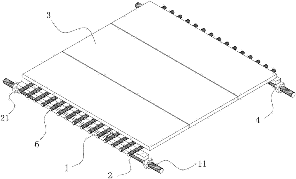
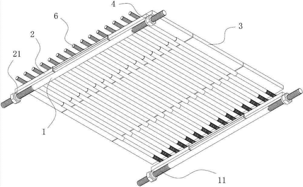
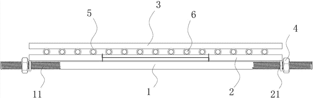
[0035] The preferred embodiment discloses a photographic vision mirror. like Figure 1 to Figure 11 As shown, the camera view mirror includes a connecting rod 1, a flexible plate 2 and a flexible mirror panel 3, and the two ends of the flexible plate 2 are respectively provided with buckles 21, and the buckle 21 is sleeved on the connecting rod 1 and can be mounted along the connecting rod 1. The extension direction moves; the flexible mirror panel 3 is installed on the flexible board 2; when the distance between the two clasps 21 is smaller than the flexible board 2, the flexible board 2 is arched, and the flexible mirror panel 3 is arched along with the flexible board 2. Wherein, the flexible board 2 is preferably made of a metal material with relatively high toughness, and the two snap rings 21 are respectively welded and mounted on both ends of the flexible board 2 .

[0036] The photographing view mirror can expand the photographing field of view of a video camera or a c...

Embodiment 2

[0047] This preferred embodiment discloses a camera assembly, including a camera or a camera head, a metering box, and the camera view mirror as described in the first preferred embodiment. The camera field of view mirror is installed in the metering box, and the bending degree of the flexible mirror panel is adjusted by changing the bending degree of the flexible plate, thereby changing the field of view of the camera or the camera, so as to ensure that a wider range of electricity stealing traces and the characteristics of the perpetrator can be photographed , the obtained image information is more evidential.


PUM


Abstract

The invention discloses a photographic field of view mirror and a photographing component, belongs to the field of photography and video recording technology and is designed to solve the problem of limited photographic field of view in the prior art. The photographic field of view mirror of the invention comprises a connecting rod, a flexible plate and a flexible mirror board. Both ends of the flexible plate are provided with retaining rings. The retaining rings sleeve the connecting rod and can move in an extending direction of the connecting rod. The flexible mirror board is mounted on the flexible plate. The flexible plate is arched when the distance between the two retaining rings is less than the flexible plate, and the flexible mirror board is arched with the flexible plate. The photographing component of the invention comprises a camera or a camera lens, and further includes the above-mentioned photographic field of view mirror. The photographic field of view mirror and the photographing component of the invention can take into account a wide range inside and outside of a metering box, and ensure that the on-site image data obtained include both an electricity stealing doer and electricity stealing behavior traces to satisfy the evidence objectivity and relevance and facilitate the use thereof in administrative law enforcement.

Description

technical field [0001] The present invention relates to the technical field of photographing and photographing, and in particular to a photographing view mirror and a photographing assembly comprising the photographing view mirror. Background technique [0002] Electricity theft evidence generally includes the model of the metering device, meter number, display number, blockade number, traces of electricity theft on the metering device or lines, and the characteristics of the perpetrator. Among them, the model, meter number, display number and block number of the metering device can be known through the system and alarm data. The traces of electricity theft on the metering device or the line and the characteristics of the perpetrator need to be provided by the evidence collection device, and the commonly used method is the camera evidence collection method. [0003] The existing video evidence collection methods have many dead spots, and even if multiple cameras are install...

Claims


Application Information

Patent Timeline
Patent Type & Authority Applications(China)
IPC IPC(8): H04N5/225G02B7/182G02B7/185
CPCG02B7/182G02B26/0825H04N23/55
Inventor 史卫华田康崔亚华龙高翼宁江田维维吴筑晖刘运兵黄宁钰
Owner ANSHUN POWER SUPPLY BUREAU
Why Eureka
Try Eureka