Turbofan

A turbo fan and blade technology, applied in the field of turbo fans, can solve problems such as decreased productivity, and achieve the effect of easy welding operation and stable support

Active Publication Date: 2017-07-14
PANASONIC INTELLECTUAL PROPERTY MANAGEMENT CO LTD
View PDF8 Cites 5 Cited by
  • Summary
  • Abstract
  • Description
  • Claims
  • Application Information

AI Technical Summary

Problems solved by technology

[0010] The problem of turbulent flow can be solved as long as the fitting part is not formed, but when welding the blade parts, means for fixing the blade parts is required, and there is a problem that the productivity drops significantly

Method used


Image

  • Turbofan
  • Turbofan
  • Turbofan

Examples


Embodiment Construction

[0071] Hereinafter, embodiments of the turbofan according to the present invention will be described with reference to the drawings.

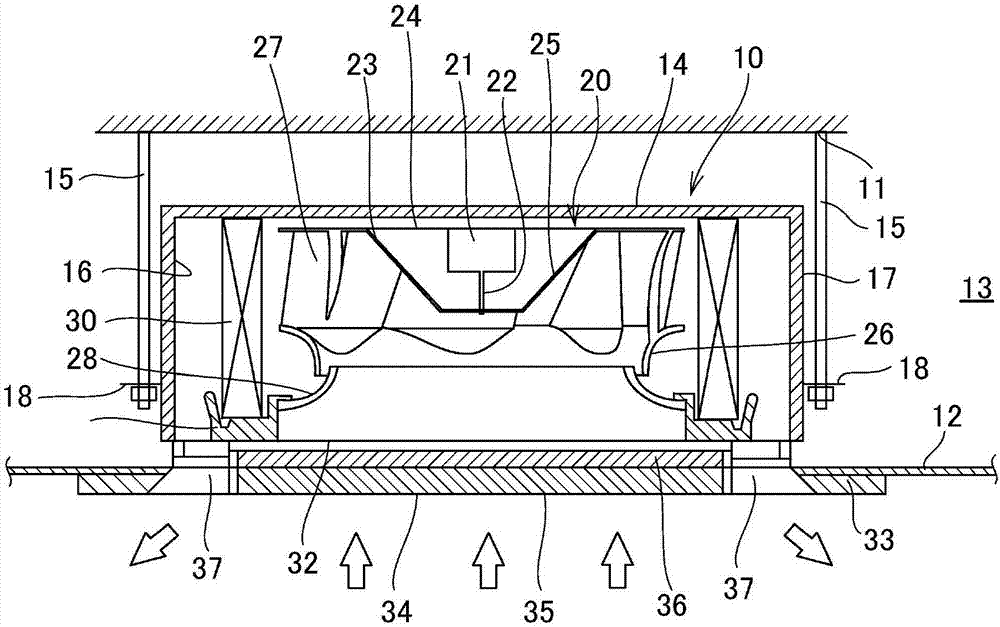
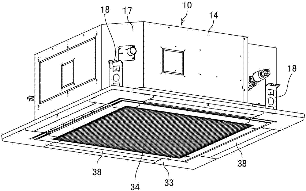
[0072] figure 1 It is a longitudinal sectional view showing an embodiment of a ceiling-mounted air conditioner to which the turbo fan of the present invention is applied. figure 2 It is a perspective view of a ceiling-mounted air conditioner.

[0073] Such as figure 1 As shown, in this embodiment, the indoor unit 10 is installed in a ceiling space 13 between a ceiling 11 of a house and a ceiling 12 provided below the ceiling 11 .

[0074] Such as figure 1 As shown, the indoor unit 10 includes an air conditioner main body 14 formed in a box shape with an open bottom, and a hanger 18 is installed at an outer corner of the air conditioner main body 14 . The air conditioner main body 14 is installed in a suspended state from the ceiling 11 by a hoist bolt 15 connected to a hanger 18 . Inside the air conditioner main body 14 , a heat insulatin...


PUM


Abstract

The invention provides a turbofan which can stably support a blade part and can easily perform welding operation. The turbofan comprises a mainboard (24), a cover (26) and a plurality of blade parts (27), wherein blade parts (27) comprise flange portions (45), the flange portions (45) are welded to the mainboard (24), so that the blade parts (27) are jointed to the mainboard (24).

Description

technical field [0001] The present invention relates to a turbo fan, and more particularly, to a turbo fan capable of stably supporting a blade member and enabling easy welding. Background technique [0002] Conventionally, there is known a turbofan mounted in an indoor unit of an air conditioner, etc., and composed of a main board, a shroud, and a plurality of wings (sheets). [0003] As such a turbofan, the prior art discloses a technique in which, for example, a main plate having a hub fixed to a rotating shaft of a motor at the center, a cover forming a suction guide wall, and a plurality of blade members are individually molded using thermoplastic resins. , the main board has a fitting portion fitted with a plurality of blade parts, and the cover has a fitting portion fitted with a plurality of blade parts, and the plurality of blade parts are fitted with a plurality of parts of the main board and the cover in a manner parallel to the rotation axis. The parts are fitte...

Claims


Application Information

Patent Timeline
IPC IPC(8): F04D25/08F04D29/30F04D29/64F04D29/70B29C65/08B29C65/78
CPCB29C65/08B29C65/7814B29C66/124B29C66/301B29C66/30223B29C66/543B29C66/8322F04D25/088F04D29/30F04D29/646F04D29/703
Inventor 内田阳一冈部清志土井康之
Owner PANASONIC INTELLECTUAL PROPERTY MANAGEMENT CO LTD
Why Eureka
Try Eureka