Eureka AIR delivers breakthrough ideas for toughest innovation challenges, trusted by R&D personnel around the world.

Special lathe support frame for worm rod machining

A special lathe and support frame technology, which is applied in the direction of metal processing equipment, metal processing machine parts, manufacturing tools, etc., can solve the problem of tedious and inaccurate angle adjustment of the whirlwind milling support frame, and achieve simple structure, easy adjustment, and rotation prevention The effect of plate rotation

Inactive Publication Date: 2017-07-11
郑州佳泰机电科技有限公司
View PDF0 Cites 2 Cited by
  • Summary
  • Abstract
  • Description
  • Claims
  • Application Information

AI Technical Summary

Problems solved by technology

[0003] The angle adjustment on the existing whirling milling support frame is cumbersome and inaccurate

Method used


Image

  • Special lathe support frame for worm rod machining
  • Special lathe support frame for worm rod machining
  • Special lathe support frame for worm rod machining

Examples


Embodiment Construction

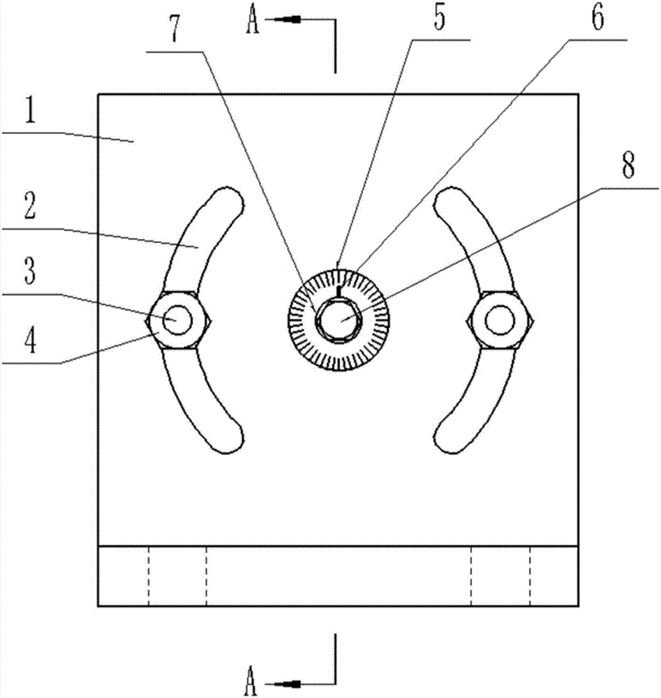
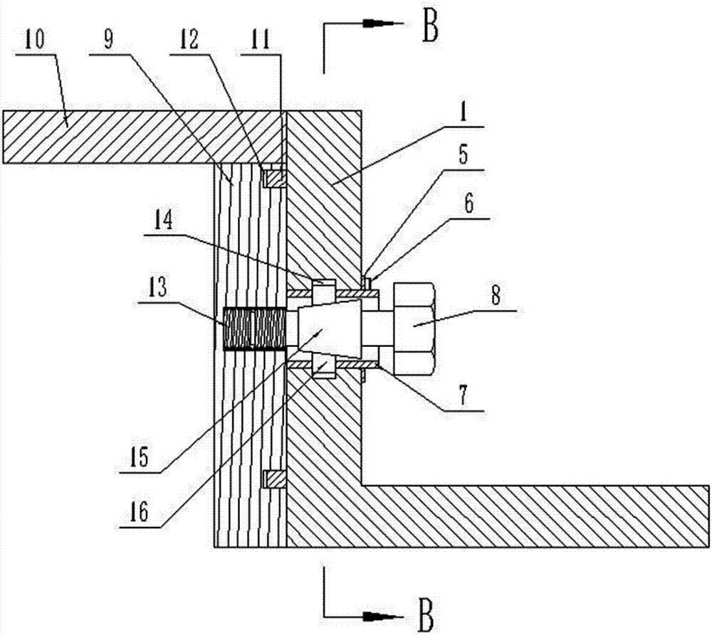
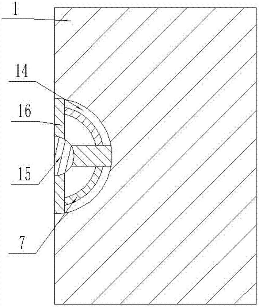
[0021] Such as figure 2 As shown, the special lathe support frame for worm processing includes the first support plate 1 whose lower end is bent to the right, the left side of the first support plate 1 is provided with an annular protrusion 11, and the left side of the first support plate 1 is provided with a The rotating plate 9 is provided with a supporting plate 10 perpendicular thereto, the right side of the rotating plate 9 is provided with an annular groove 12 cooperating with the annular protrusion 11, and the annular protrusion 11 is arranged in the annular groove 12, The right side of the rotary plate 9 is provided with a shaft sleeve 7 coaxial therewith, and the shaft sleeve 7 extends rightward through the first support plate 1 and the dial 5 provided on the right side of the first support plate 1. The dial 5 The shaft sleeve 7 on the right side is provided with a pointer 6, and the bolt 8 passes through the shaft sleeve 7 and is threadedly connected with the thread...


PUM


Abstract

The invention relates to the field of machining equipment, in particular to a special lathe support frame for worm rod machining. The special lathe support frame for worm rod machining comprises a first support plate; an annular convex block is arranged on the left side surface of the first support plate; a rotating plate is arranged on the left side of the first support plate; an annular groove is formed in the right side surface of the rotating plate; a shaft sleeve is arranged on the right side of the rotating plate, and extends to the right side to penetrate through the first support plate and an indexing plate arranged on the right side surface of the first support plate; a pointer is arranged on the shaft sleeve on the right side of the indexing plate; a bolt penetrates through the shaft sleeve to be in threaded connection with a thread hole on the rotating plate; a circular table is arranged at the middle part of the bolt; a groove hole is formed in the first support plate; multiple stoppers are uniformly distributed in the groove hole; one ends of the stoppers penetrate through the shaft sleeve to extend in the axial center line direction of the shaft sleeve; and a screw rod is arranged on the rotating plate, and penetrates through an arc hole on the first support plate. The special lathe support frame for worm rod machining is simple in structure, convenient to operate, liable to adjust the rotating angle and low in cost, and meanwhile, effectively prevents the rotating problem of the rotating plate caused by vibration.

Description

technical field [0001] The invention relates to the field of mechanical processing equipment, in particular to a special lathe support frame for worm processing. Background technique [0002] The special lathe for worm processing mainly adopts the equipment of cyclone milling. The motor and whirling milling cutter are installed on the lathe through the support frame to process the worm, and there is still a degree of freedom to adjust the helix angle within a certain angle range when whirling milling the worm, so the support frame is required to have the function of rotating the cutting tool. [0003] The angle adjustment on the existing whirling milling support frame is cumbersome and inaccurate. Contents of the invention [0004] The technical problem to be solved by the present invention is a special lathe support frame for worm machining which has a simple structure, is easy to adjust the rotation angle, and prevents loosening. [0005] In order to achieve the above ...

Claims


Application Information

Patent Timeline
Patent Type & Authority Applications(China)
IPC IPC(8): B23Q1/25
CPCB23Q1/25
Inventor 樊育东
Owner 郑州佳泰机电科技有限公司
Why Eureka
Eureka Blog
Learn More