
Method for acquiring stress states of metallic frameworks of power assembly suspension system

A powertrain and metal skeleton technology is applied in the field of simulation analysis of vehicle powertrain mounting systems, which can solve the installation constraints that cannot reflect the relative motion and contact relationship between the active and passive ends of the mount, and cannot reflect the energy-absorbing effect of rubber. Problems such as low reliability of analysis results

Active Publication Date: 2017-07-07
JIANGLING MOTORS
View PDF3 Cites 6 Cited by
  • Summary
  • Abstract
  • Description
  • Claims
  • Application Information

AI Technical Summary

Problems solved by technology

[0004] The above-mentioned analysis method has the following problems. First, the work of extracting loads through multi-body simulation is cumbersome and the workload is large. Secondly, since the loads extracted during multi-body simulation analysis are at the center point of the suspension, the analysis model needs to be modified during the application process. Simplified, and the active and passive ends of the mount need to be calculated separately, which cannot reflect the relative movement and contact relationship between the active and passive ends of the mount, nor can it reflect the energy absorption effect of the rubber in the mount and the installation constraints of the system, so it cannot be simulated Simulate the real working state of the powertrain mounting system, so that the possible strength risk cannot be exposed. At the same time, since the powertrain mounting system works, all metal skeletons work together, and the method of analyzing individual metal skeletons one by one is adopted. Clearly there are major flaws
Therefore, the error of the force state obtained by the above analysis method is relatively large, which leads to low reliability of the analysis results and cannot serve as a good reference

Method used


Image

  • Method for acquiring stress states of metallic frameworks of power assembly suspension system
  • Method for acquiring stress states of metallic frameworks of power assembly suspension system
  • Method for acquiring stress states of metallic frameworks of power assembly suspension system

Examples


Embodiment Construction

[0046] In order to facilitate the understanding of the present invention, the present invention will be described more fully below with reference to the associated drawings. Several embodiments of the invention are shown in the drawings. However, the present invention can be embodied in many different forms and is not limited to the embodiments described herein. Rather, these embodiments are provided so that the disclosure of the present invention will be thorough and complete.

[0047] It should be noted that when an element is referred to as being “fixed on” another element, it may be directly on the other element or there may be an intervening element. When an element is referred to as being "connected to" another element, it can be directly connected to the other element or intervening elements may also be present. The terms "vertical," "horizontal," "left," "right," and similar expressions are used herein for purposes of illustration only.

[0048] Unless otherwise def...


PUM


Abstract

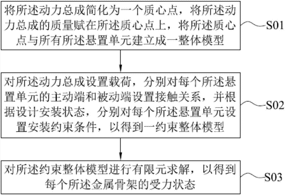
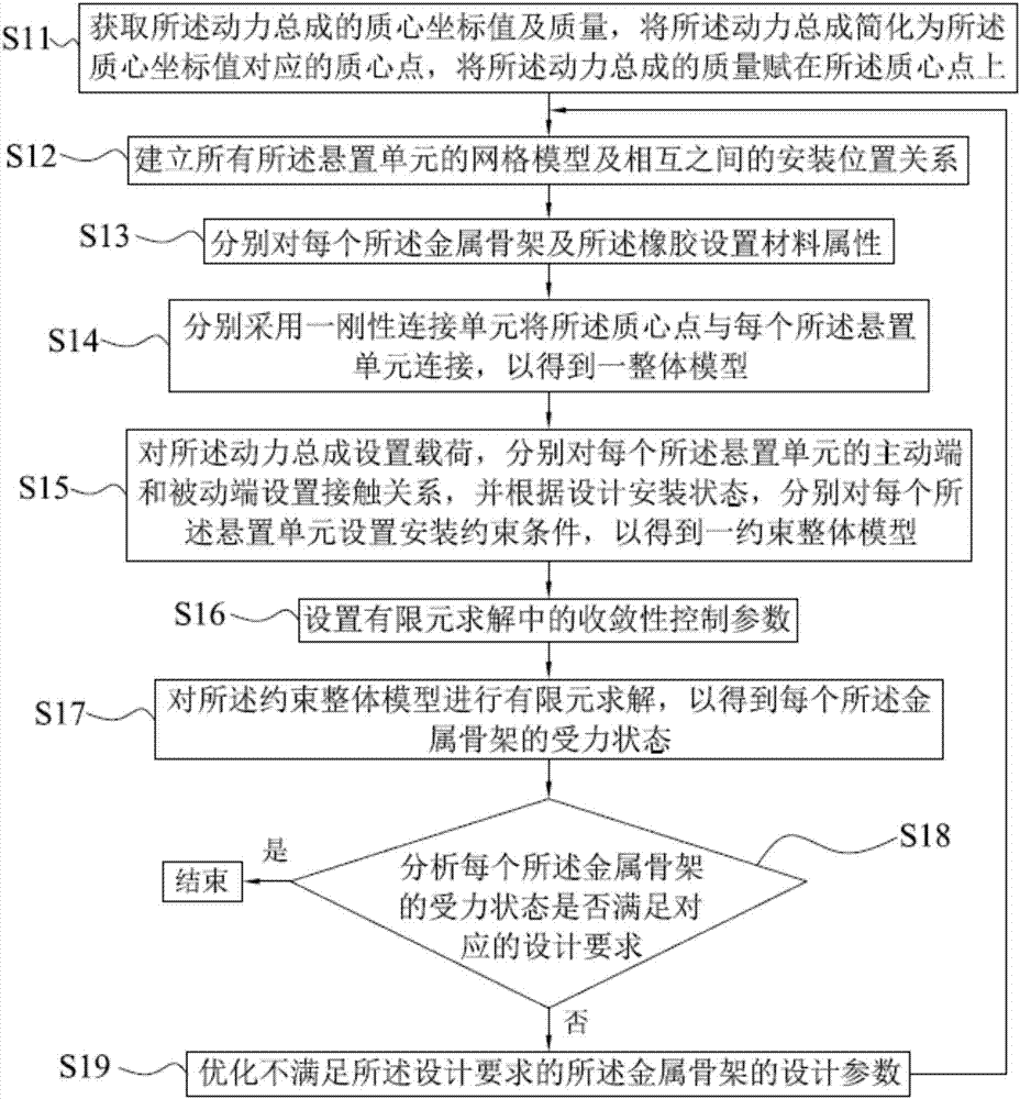
The invention provides a method for acquiring stress states of metallic frameworks of a power assembly suspension system. The power assembly suspension system comprises at least one suspension unit used for supporting a power assembly. Each suspension unit comprises a metallic framework and rubber. The method comprises the steps that the power assembly is simplified to be a centroid point, the mass of the power assembly is assigned to the centroid point, and the centroid point and all the suspension units are made into an overall model; a load is set for the power assembly suspension system, a contact relation is set for the driving end and the driven end of each suspension unit, and an installation constraint condition is set for each suspension unit according to a designed installation state to obtain a constraint overall model; and the constraint overall model is subjected to finite element solution to obtain the stress state of each metallic framework. Through the method for acquiring the stress states of the metallic frameworks of the power assembly suspension system, the actual work state of the power assembly suspension system can be truly simulated, and therefore the reliability of the acquired stress states of the metallic frameworks is high.

Description

technical field [0001] The invention relates to the technical field of simulation analysis of an automobile powertrain mount system, in particular to a method for acquiring a force state of a metal skeleton of a powertrain mount system. Background technique [0002] The powertrain suspension system is a key component of the car, and its importance to the safety and comfort of the vehicle is self-evident. The powertrain suspension system includes powertrain and suspension units, among which there are various types of suspension units, and the most widely used is rubber suspension, which is composed of rubber and metal skeleton. During the actual use of the vehicle, the harsh working environment and load conditions may cause wear or fracture of the metal frame. Therefore, in the development process of the powertrain mount system, it is necessary to ensure that the mount unit has sufficient strength performance, which is usually achieved by CAE analysis of the strength of the ...

Claims


Application Information

Patent Timeline
Patent Type & Authority Applications(China)
IPC IPC(8): G06F17/50
CPCG06F30/15G06F30/23
Inventor 赖余东段龙杨余显忠黄晖邱星文新海邱祖峰何君儒张良
Owner JIANGLING MOTORS
Learn More