Heater and heating non-combustion electronic cigarette

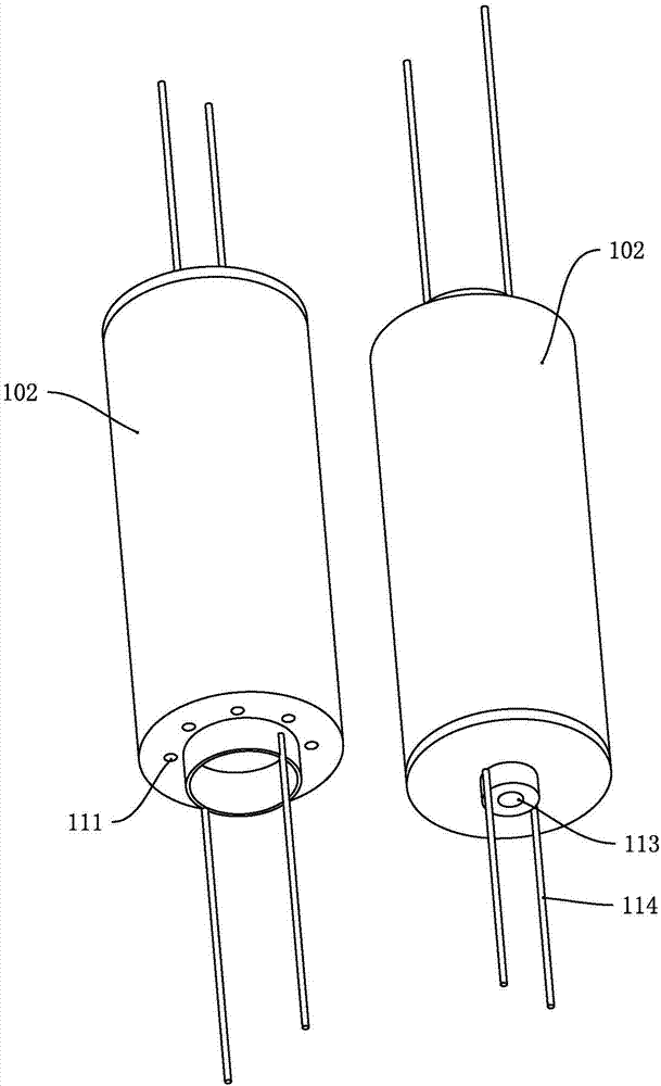
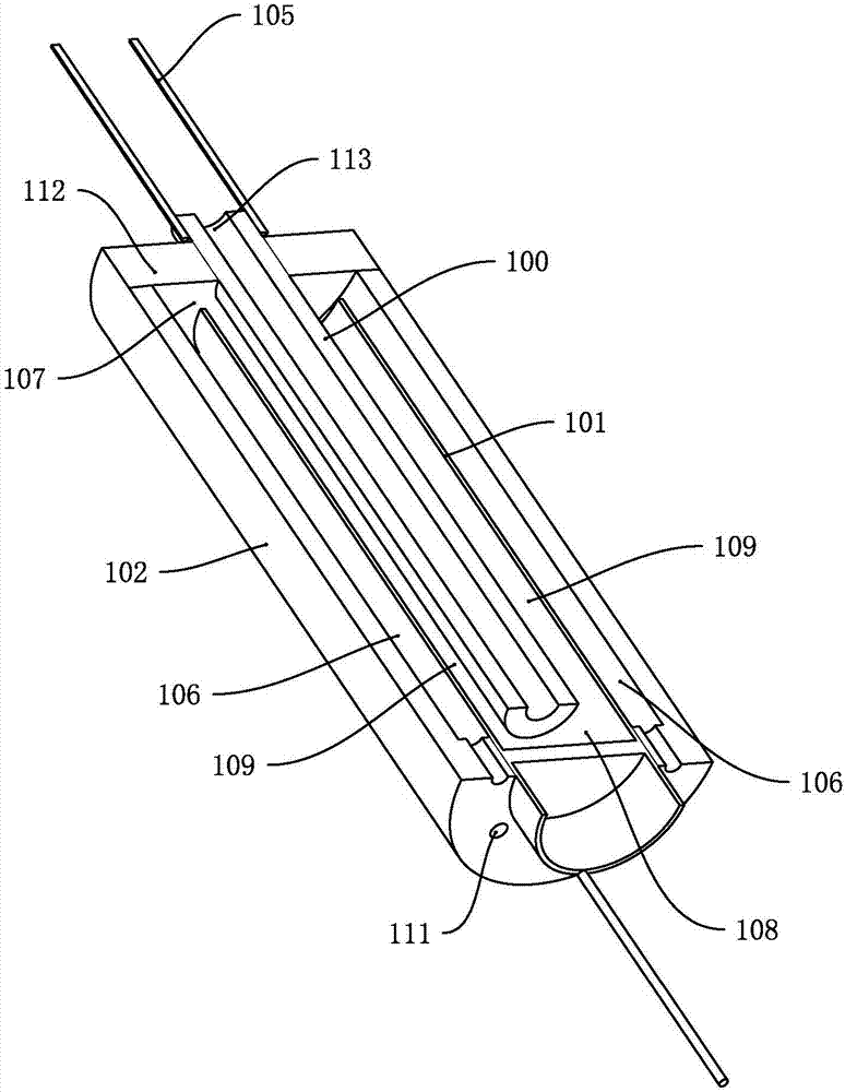
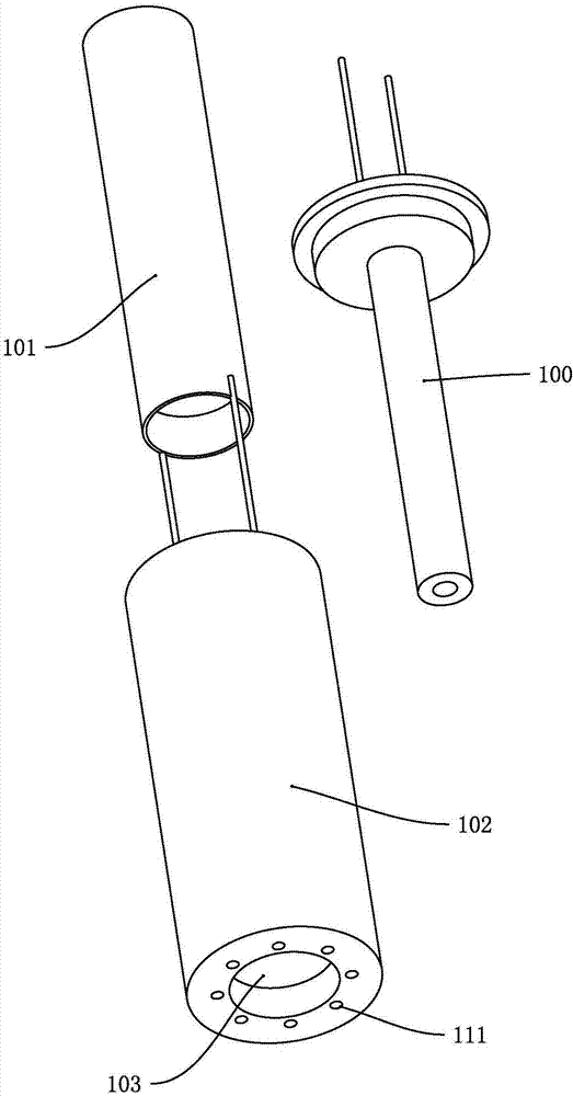
A technology of a heater and a heating body, applied in the field of electronic cigarettes, can solve the problems such as the difficulty of rapidly increasing the heating temperature of the heating body, the uneven temperature of the tobacco, and the short length of the heating body, so as to reduce the thermal insulation burden, prolong the heating path and time, the effect of increasing the heating stroke

Pending Publication Date: 2017-07-04
廖向阳
View PDF6 Cites 14 Cited by
  • Summary
  • Abstract
  • Description
  • Claims
  • Application Information

AI Technical Summary

Problems solved by technology

[0002] The existing tobacco electronic cigarette heating method is to put the tobacco in the heating cup and bake it through the heating body, which belongs to contact heating. The temperature in the area of ​​the heating cup is low, resulting in uneven tobacco temperature during the heating process, failing to fully heat the entire tobacco, resulting in waste and unsatisfactory taste; at the same time, due to the short length of the heating body, it is difficult to quickly increase the temperature heated by the heating body

Method used


Image

  • Heater and heating non-combustion electronic cigarette
  • Heater and heating non-combustion electronic cigarette
  • Heater and heating non-combustion electronic cigarette

Examples


no. 2 example

[0031] Second embodiment, such as Figure 5 As shown, the difference between this embodiment and the first embodiment is: several layers of middle heating bodies 115 between the inner layer heating body 100 and the outer layer heating body 101, and the middle layer heating body 115 and the inner layer heating body 100 and Middle layer airflow heating channels are formed between the outer layer heating bodies 101 . The middle heating body 115 can be two layers, four layers, six layers or other even-numbered layers. A middle airflow heating channel is formed between the middle heating body 115 and the middle heating body 115 , and the structure of two adjacent middle heating bodies 115 is the same or similar to that of the inner heating body 100 or the outer heating body 101 . Increase the number of roundabout flows of air in the heating body, further increase the heating stroke and heating time, and at the same time increase the level of heating to obtain a higher temperature,...

no. 3 example

[0032] The third embodiment, such as Figure 6 As shown, the difference between this embodiment and the first embodiment is: the outer wall of the outer layer heating body 101 is provided with a first spiral protrusion, and the first spiral protrusion and the inner wall of the heat insulation sleeve 102 form a first spiral heating channel. The outer wall of the inner heating body 100 is provided with a second spiral protrusion, and the second spiral protrusion forms a second spiral heating channel with the inner wall of the outer heating body 101 . The air moves along the first spiral heating channel and the second spiral heating channel respectively, which prolongs the air heating stroke and heating time.

[0033] Fourth embodiment, such as Figure 7 to Figure 9As shown, the difference between this embodiment and the first embodiment is: the outer wall of the outer layer heating body 101 is covered with a first spiral member 200, and the first spiral member 200 and the inner...

no. 5 example

[0035] The fifth embodiment, the difference between this embodiment and the first embodiment is that the inner wall of the inner layer heating body 100 and the inner wall of the outer layer heating body 101 are respectively provided with inner spiral grooves. When the air is heated in the inner layer airflow heating channel 109 and the inner layer heating body 100, the air flows along the inner helical groove of the outer layer heating body 101 and the inner helical groove of the inner layer heating body 100 respectively, thus further increasing the air flow. The heating stroke and heating time further increase the temperature of the air flowing out from the inner layer heating body 100 .


PUM


Abstract

The invention discloses a heater and a heating non-combustion electronic cigarette. The heater comprises an inner layer heating body, an outer layer heating body and a heat insulation sleeve; the front end of the outer layer heating body is a closed end, and the rear end of the outer layer heating body is an open end; both ends of the inner layer heating body respectively are open ends; a first through hole runs through the front end face of the heat insulation sleeve, and a second through hole runs through the rear end face of the heat insulation sleeve; the outer layer heating body is sleeved with the heat insulation sleeve, and an outer layer gas flow heating passage is formed between the outer layer heating body and the inner wall of the heat insulation sleeve; the front end of the outer layer heating body and the inner wall of the first through hole form sealed connection; the inner layer heating body is sleeved with the outer layer heating body, and an inner layer gas flow heating passage is formed between the inner layer heating body and the inner wall of the outer layer heating body; the rear end of the inner layer heating body and the inner wall of the second through hole form sealed connection; a plurality of gas inlet holes communicated with the outer layer gas flow heating passage run through the front end face of the heat insulation sleeve. The heating non-combustion electronic cigarette comprises the heater and has the advantages that a heating stroke and heating time of air can be increased, the size is small, and a heating temperature is stably increased.

Description

technical field [0001] The invention relates to an electronic cigarette, in particular to a heater and a heat-not-burn electronic cigarette. Background technique [0002] The existing tobacco electronic cigarette heating method is to put the tobacco in the heating cup and bake it through the heating body, which belongs to contact heating. The temperature in the area of ​​the heating cup is low, resulting in uneven temperature of the tobacco during the heating process, failing to fully heat the entire tobacco, resulting in waste and unsatisfactory taste; at the same time, due to the short length of the heating body, it is difficult to quickly increase the temperature heated by the heating body . Contents of the invention [0003] The purpose of the present invention is to solve the deficiencies of the prior art, and provide a heater and a heat-not-burn electronic cigarette. [0004] A kind of technical scheme of the present invention: [0005] A heater, comprising a holl...

Claims


Application Information

Patent Timeline
Patent Type & Authority Applications(China)
IPC IPC(8): A24F47/00
Inventor 廖向阳
Owner 廖向阳
Why Eureka
Try Eureka