
Cloth cutting device

A cloth and cutting technology, applied in the cutting of textile materials, textiles and papermaking, metal processing, etc., can solve the problems of reducing production efficiency, reducing cutting efficiency, increasing the burden on operators, etc., to achieve efficient cutting work and good practicability Effect

Active Publication Date: 2017-06-27
浙江斯泰堡纺织有限公司
View PDF7 Cites 20 Cited by
  • Summary
  • Abstract
  • Description
  • Claims
  • Application Information

AI Technical Summary

Problems solved by technology

Among them, in the sewing process of the cloth, the existing needle plate installed on the common single-needle flat car can only provide the needles of the common single-needle flat car with the cooperation effect of sewing processing, but cannot be used for sewing before and after sewing. Neutralize the fabric after sewing for any cutting process; when it is necessary to cut the fabric before, during and after sewing, the usual method is to cut the fabric by the operator with scissors, Correspondingly reduce the cutting efficiency; when the cloth to be cut is fabric or interlining, since the fabric or interlining is relatively thick and has a relatively high hardness, pure manual operation will further increase the burden on the operator, thereby reducing production efficiency

Method used


Image

  • Cloth cutting device
  • Cloth cutting device
  • Cloth cutting device

Examples


Embodiment Construction

[0014] Below in conjunction with accompanying drawing, concrete structure among the present invention is described:

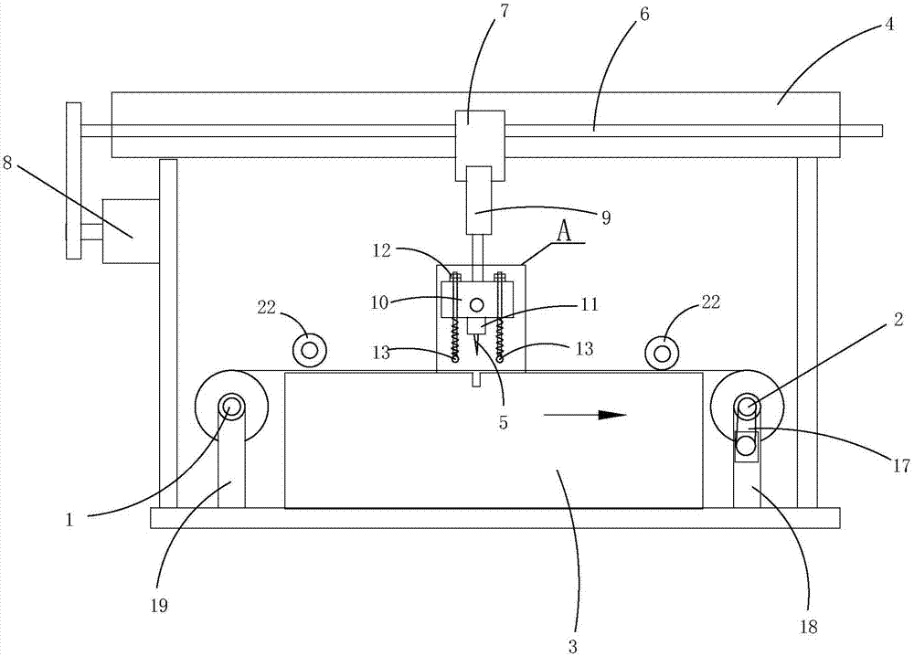
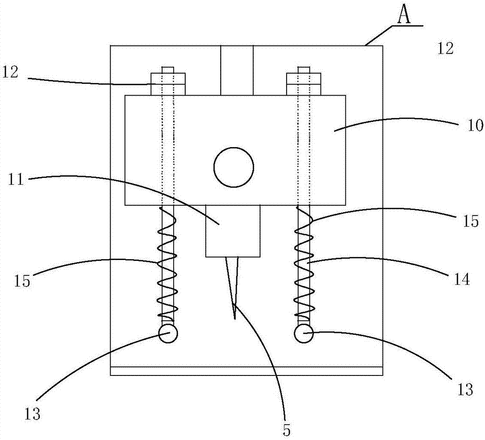
[0015] Such as Figure 1 to Figure 3 As shown, the cloth cutting device of this embodiment includes an unwinding positioning shaft 1 and a winding positioning shaft 2 arranged in parallel in the horizontal direction, and a positioning shaft 1 arranged between the unwinding positioning shaft 1 and the winding positioning shaft 2. The support platform 3, the gantry 4 located above the unwinding positioning shaft 1 and the rewinding positioning shaft 2, the cutter 5 for cutting the cloth, and the gantry 4 installed on the gantry 4 to drive the cutting knife 5 to move Drive mechanism; The drive mechanism includes along the cloth conveying direction (ie figure 1 The direction indicated by the middle arrow) is arranged on the screw mandrel 6 on the gantry frame 4, and the mobile frame 7 that is threadedly matched with the screw mandrel 6 and can carry out screw tran...


PUM


Abstract

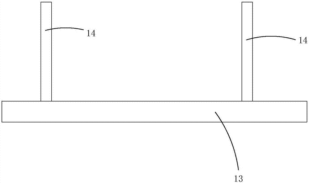
The invention discloses a cloth cutting device. The cloth cutting device comprises an uncoiling positioning rotary shaft, a supporting platform, a gantry, a cutter and a driving mechanism, wherein the driving mechanism comprises a screw rod, a moving rack, a motor, a cylinder, an assembly rack, a cutter rest and a driving mechanism; the cutter is arranged on the cutter rest; cloth pressing bars are arranged on two sides of the cutter rest on the assembly rack; the cloth pressing bars are arranged along the width direction of a cloth; the length of the cloth pressing bars is not smaller than the width of the cloth; the cloth pressing bars are movably arranged on the assembly rack through a plurality of elastic connection components; each elastic connection component comprises a connection rod and a spiral spring; the lower end of each connection rod is fixedly connected with the corresponding cloth pressing bar through welding; the upper end of each connection rod penetrates through a vertical through hole in the moving rack and then is fixedly connected with a baffle block; the outer diameter of each baffle block is larger than the hole diameter of each vertical through hole, so that each connection rod is limited in the corresponding vertical through hole to move vertically; and the upper and lower ends of each spiral spring are separately resisted against the assembly rack and the corresponding cloth pressing bar. By adopting the cloth cutting device, the cloth can be cut high efficiently; and the cloth cutting device has very good practicability.

Description

technical field [0001] The invention relates to a cloth cutting device. Background technique [0002] With the continuous development of the economy and the continuous improvement of people's living standards, people put forward new requirements for the quality and types of various consumer goods to meet people's individual pursuits, and decorative fabrics are one of the many consumer goods. As we all know, cloth needs to involve many processes before it is made into a finished product. Among them, in the sewing process of the cloth, the existing needle plate installed on the common single-needle flat car can only provide the needles of the common single-needle flat car with the cooperation effect of sewing processing, but cannot be used for sewing before and after sewing. Neutralize the fabric after sewing for any cutting process; when it is necessary to cut the fabric before, during and after sewing, the usual method is to cut the fabric by the operator with scissors, Co...

Claims


Application Information

Patent Timeline
IPC IPC(8): B26D1/08B26D7/02B26D5/06D06H7/00
CPCB26D1/085B26D5/06B26D7/015B26D7/025D06H7/00
Inventor 张平
Owner 浙江斯泰堡纺织有限公司
Learn More