A Dry Venturi Paint Spraying System

A venturi and dry technology, applied in spray booths, spray devices, etc., can solve the problems of poor working environment of paint mist trapping box, poor working environment of paint mist trapping box, low investment and so on, so as to reduce cleaning and maintenance. Work load, reduce pollution and energy consumption, and facilitate the effect of walking

Active Publication Date: 2021-08-06
嘉兴启净涂装科技有限公司
View PDF7 Cites 0 Cited by
  • Summary
  • Abstract
  • Description
  • Claims
  • Application Information

AI Technical Summary

Problems solved by technology

However, the paint spraying system with this layout needs to replace the disposable paint mist collection box from the inside of the paint mist diversion chamber, and the working environment for replacing the paint mist collection box is not good.
The paint spraying system of this structure is compact in structure and low in investment, but the operating environment for changing the paint mist collection box is poor, and it is only suitable for relatively low investment and small occasions in space, such as the patent with publication number 104858095A

Method used


Image

  • A Dry Venturi Paint Spraying System
  • A Dry Venturi Paint Spraying System
  • A Dry Venturi Paint Spraying System

Examples


Embodiment 1

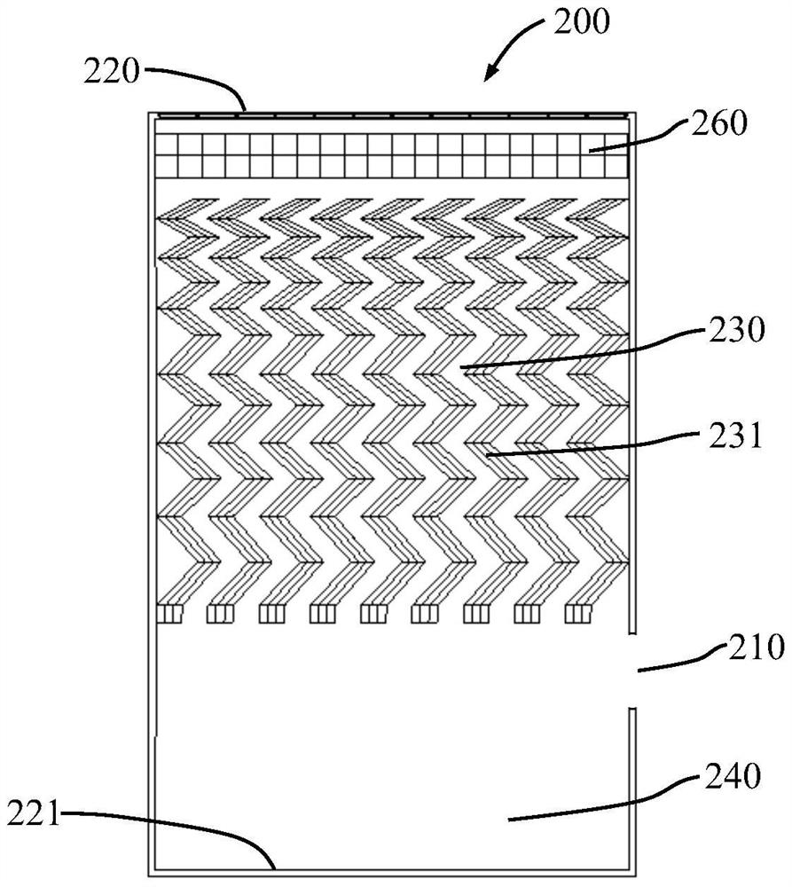
[0072] Such as image 3 As shown, nine paint mist trapping units 231 of the same size and shape are set in the paint mist trapping chamber 230 of this embodiment. The paint mist trapping unit is a corrugated plate structure with 13 bends, and each paint mist trap The capture unit has 1 air drainage surface and 13 bending surfaces. The bending angle of the bending surface gradually increases along the mainstream direction of the air. The 9 paint mist capture units are arranged parallel to the mainstream direction of the air, parallel to each other and Evenly distributed with equal gaps in between. The gap between two adjacent paint mist capture units forms an air flow channel with 13 bends. Since the bending angle of the paint mist capture units along the mainstream direction of the air gradually increases, the two paint mist capture units The width of the bent air flow channel formed by the gap between them also gradually narrows along the air main flow direction. The paint ...

Embodiment 2

[0074] Such as Figure 4 As shown, several rows of paint mist collection units 231 are arranged in the paint mist collection chamber of the present embodiment, and the distance between the paint mist collection units in the same row is the same. The bottom five rows of paint mist collection units have the same size and equal row spacing, and the opening direction of the last row of paint mist collection units forms an angle of 60 to 90 degrees with the opening direction of the next row of paint mist collection units. Among the bottom five rows of paint mist collection units, the space directly below the paint drainage head of the last row of paint mist collection units is the gap between the next row of paint mist collection units. The size of the paint mist collecting units in the upper four rows is smaller than that in the lower five rows, and the distance between the paint mist collecting units in the same row and the distance between two rows are also smaller than those in...


PUM


Abstract

The invention relates to a disposable paint mist trapping device and a dry Venturi paint spraying system applied thereto. The lower part of the paint mist trapping device is provided with a paint collection chamber, the middle part is provided with a paint mist trapping chamber, and the upper part is provided with a sheet filter. Floor. The air inlet of the device is arranged on the upper part of one side of the paint collection chamber, and the air outlet is arranged on the top of the paint mist collecting device. The dry Venturi painting system uses the above-mentioned disposable paint mist trapping device as a separate component, and the paint mist trapping device is installed in the installation room of the paint mist trapping device. The installation room of the paint mist collection device is arranged outside the air diversion chamber, and the installation room of the paint mist collection device and the air diversion chamber are connected by a Venturi channel. The venturi channel extends into the interior of the installed paint mist trap and towards the bottom of the paint mist trap. Compared with the prior art, the present invention has stable performance, convenient operation, large capacity for collecting and accommodating paint mist, and is energy-saving and environment-friendly.

Description

technical field [0001] The invention relates to the field of industrial coating, especially to the field of trapping, separating and collecting sprayed overspray, in particular to a disposable dry paint mist trapping device and its applied dry Venturi paint spraying system, widely used Applied to the coating of automobiles, hardware, home appliances, toys, etc. Background technique [0002] With the rapid development of China's economy, environmental pollution has become more and more serious. In recent years, smog has occurred frequently, and water pollution and soil pollution have become more and more serious. Painting is a highly polluting and energy-intensive industry. During the coating production process, a large amount of exhaust gas, waste liquid and solid waste will be generated. In order to maintain the constant temperature and humidity conditions required for painting, a large amount of electric energy and fossil fuels are also consumed. [0003] The tradition...

Claims


Application Information

Patent Timeline
Patent Type & Authority Patents(China)
IPC IPC(8): B05B14/00B05B14/40B05B14/43
CPCB05B13/02B05B12/16B05B16/00
Inventor 周小参
Owner 嘉兴启净涂装科技有限公司
Why Eureka
Try Eureka