
Hybrid type tilting rotor-wing unmanned aerial vehicle

A technology for tilting rotors and unmanned aerial vehicles, which is applied in the directions of rotorcraft, unmanned aerial vehicles, motor vehicles, etc., can solve the problems of affecting vertical flight performance, increasing the flight resistance of aircraft structure weight, affecting aircraft level flight performance, etc. To achieve the effect of simple vertical operation, high reliability, and increased design space

Pending Publication Date: 2017-06-23
北京天宇新超航空科技有限公司
View PDF6 Cites 23 Cited by
  • Summary
  • Abstract
  • Description
  • Claims
  • Application Information

AI Technical Summary

Problems solved by technology

On the one hand, in the design of the power end of the tail, most propellers are used for propulsion. In level flight, if the tail does not provide power output, large resistance will be generated, which will affect the performance of the aircraft in level flight
On the other hand, the two front power compartments are installed in the wings, which will cause most of the downwash flow generated by the propeller to be blocked by the wing surface when the aircraft is in vertical flight, causing serious power loss and affecting the vertical flight performance
In the scheme of the patent publication number CN 105775122 A, although the two front power cabins are not blocked by the wings, the existence of the connecting rod increases the structural weight of the aircraft and the flight resistance during peaceful flight

Method used


Image

  • Hybrid type tilting rotor-wing unmanned aerial vehicle
  • Hybrid type tilting rotor-wing unmanned aerial vehicle
  • Hybrid type tilting rotor-wing unmanned aerial vehicle

Examples


Embodiment Construction

[0024] In order to make the technical problems, technical solutions and beneficial effects solved by the present invention clearer, the present invention will be further described in detail below in conjunction with the accompanying drawings and embodiments. It should be understood that the specific embodiments described here are only used to explain the present invention, not to limit the present invention.

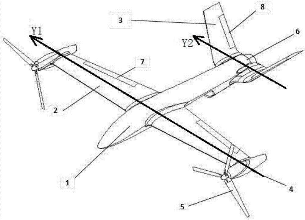
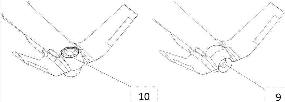
[0025] The wing power cabin 4 can rotate around the rotation axis Y1, and the ducted power cabin 6 can rotate around the rotation axis Y2 in the vertical plane where the central axis of the aircraft is located. The switching between the rotor mode and the fixed wing mode is realized through the control of the tilting mechanism.

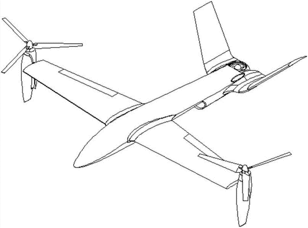
[0026] When the UAV is in multi-rotor mode, the wing propeller power cabin 4 tilts upward to be perpendicular to the axis of the fuselage 1, and the ducted power cabin 6 tilts downward to be perpendicular to the axis of the fuselage 1, both of wh...


PUM


Abstract

The invention provides a hybrid type tilting rotor-wing unmanned aerial vehicle. The hybrid type tilting rotor-wing unmanned aerial vehicle comprises a vehicle body, a power system, a control system and a tilting mechanism. The vehicle body comprises a fuselage, wings and an empennage; the power system is composed of screw propeller power cabins which are located at two ends of the wings and a tail duct power cabin; each power cabin can be tilted for a large angle; the control system can be used for carrying out stabilization and posture control on parallel flight and vertical flight states of the unmanned aerial vehicle; the tilting mechanism is responsible for changing tilting angles of the three power cabins. When the unmanned aerial vehicle is at a multi-rotor-wing mode, the unmanned aerial vehicle can vertically ascend and descend and suspend in the air; when the unmanned aerial vehicle is at a fixed-wing mode, the flight speed is relatively rapid and the efficiency is relatively high. The hybrid type tilting rotor-wing unmanned aerial vehicle fuses advantages of multi-rotor wings and a fixed wing, and has wide application prospect.

Description

technical field [0001] The invention belongs to the technical field of aviation vehicle design, and in particular relates to a tilting-rotor unmanned aerial vehicle. Background technique [0002] For a long time, people have been looking for an aircraft that combines the advantages of multi-rotor aircraft and fixed-wing aircraft. After years of exploration and practice, such as the first generation of American tilt-rotor prototype verification aircraft XV-15, the already-serviced V-22 "Osprey" tilt-rotor aircraft, "Hawkeye" tilt-rotor UAV, etc. Military and civilian fields have played an important role and have broad development prospects. Tilt-rotor UAV not only has the advantages of multi-rotor UAV vertical take-off and landing, hovering in the air, but also has the same flight speed, range and load capacity as fixed-wing aircraft. However, because the Osprey is a tiltrotor aircraft with dual power cabins, the flight control system is relatively complicated. In vertical ...

Claims


Application Information

Patent Timeline
IPC IPC(8): B64C27/28B64C27/12
CPCB64C27/12B64C27/28B64U10/00B64U50/11B64U10/25B64U50/19B64U30/10B64U30/20
Inventor 胡龙王一博
Owner 北京天宇新超航空科技有限公司
Learn More