Air purification method of fiber dust remover

An air purification and dust collector technology, applied in chemical instruments and methods, separation methods, dispersed particle separation, etc., can solve problems such as affecting exhaust gas discharge, large noise, and reduction of dust removal effects, to ensure dust removal cleanliness, reduce noise, Dust quiet effect

Inactive Publication Date: 2017-06-23
苏州中环建科环境科技有限公司
View PDF5 Cites 0 Cited by
  • Summary
  • Abstract
  • Description
  • Claims
  • Application Information

AI Technical Summary

Problems solved by technology

[0003] The wet dust collector is commonly known as "water dust collector". It makes the dusty gas and the liquid come into close contact, and uses the inertial collision of water droplets and particles or the full mixing of water and dust and other functions to trap particles or increase the size of the particles or leave them behind. A device that achieves the separation effect of water and dust in a fixed container; the current commonly used wet dust collector directly passes the dust-containing gas into the water chamber, and the air bubbles and water film are generated in the water body through the air flow, thereby realizing dust removal; this dust removal method will produce Loud noise affects the normal life and work of the surrounding and staff; at the same time, this dust removal method will hinder the airflow speed and affect the discharge of exhaust gas; in addition, the water in the water chamber is not replaced within a cycle, and the gas in the early stage of dust removal will affect the water quality. Cause a certain amount of pollution, so that in the middle and late stages of each water change cycle, the cleanliness of the water quality will decline, so the dust removal effect in the middle and late stages will be greatly reduced

Method used


Image

  • Air purification method of fiber dust remover
  • Air purification method of fiber dust remover

Examples


Embodiment

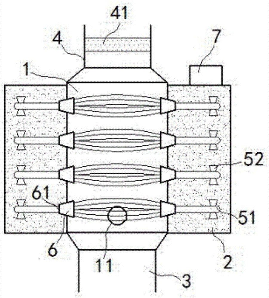
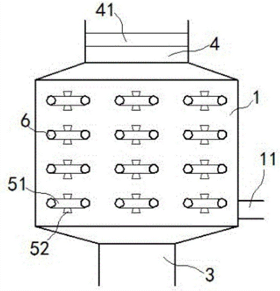
[0015] exist figure 1 , figure 2 In the shown embodiment, the fiber dust collector includes an air intake pipe 11, a dust removal chamber 1, an ash hopper 3, an exhaust pipe 4 and a cleaning chamber 2; 11 is placed at the lower end of the side wall of the dust removal chamber 1, the exhaust pipe 4 is placed at the upper end of the dust removal chamber 1, and a dryer 41 is installed in the exhaust pipe 4; the cleaning chamber 2 is installed on both sides of the dust removal chamber 1 ; Cleaning agent is filled in the cleaning chamber 2; cleaning units are arranged in an equidistant array in the dust removal chamber 1; each of the cleaning units includes a long elliptical fiber ring 51 and a driving wheel 52; The driving runner 52 is equidistantly installed in the cleaning chamber 2, and the two round ends of the fiber ring 51 pass through the sidewalls on both sides of the dust removal chamber 1 respectively, and the two round ends are sleeved on the driving runner 52. Drive...


PUM


Abstract

The invention relates to an air purification method of a fiber dust remover. The fiber dust remover comprises an air inlet pipe, a dust removal cavity, an ash bucket, an exhaust pipe and a cleaning cavity, wherein the exhaust pipe is arranged at the upper end of the dust removal cavity; the cleaning cavity is arranged on two sides of the dust removal cavity; the cleaning cavity is filled with a cleanser; cleaning units are arranged in an equidistant array in the dust removal cavity; each cleaning unit comprises long and elliptical fiber rings and driving rotating wheels; the driving rotating wheels are arranged equidistantly in the cleaning cavity, two round ends of each fiber ring penetrate out of side walls on two sides of the dust removal cavity respectively, and the two round ends are sleeved on the driving rotating wheels and driven by the driving rotating wheels to move; a trumpet cover is arranged at a contact position between each fiber ring and the side wall of the dust removal cavity, and the caliber of a small port of the trumpet cover is smaller than the radius of the fiber ring; and the small port of each trumpet cover faces the cleaning cavity. The dust remover has a novel structure, can remove dust efficiently, and is quiet and energy-saving during dust removal.

Description

[0001] This application is a divisional application of the Chinese invention patent application filed on January 8, 2016 with the application number 201610010489.X and the invention name being fiber dust collector. technical field [0002] The invention relates to a dust collector, in particular to an air purification method for a wet dust collector. Background technique [0003] The wet dust collector is commonly known as "water dust collector". It makes the dusty gas and the liquid come into close contact, and uses the inertial collision of water droplets and particles or the full mixing of water and dust and other functions to trap particles or increase the size of the particles or leave them behind. A device that achieves the separation effect of water and dust in a fixed container; the current commonly used wet dust collector directly passes the dust-containing gas into the water chamber, and the air bubbles and water film are generated in the water body through the ai...

Claims


Application Information

Patent Timeline
Patent Type & Authority Applications(China)
IPC IPC(8): B01D50/00
CPCB01D50/00B01D50/40
Inventor 安双志
Owner 苏州中环建科环境科技有限公司
Why Eureka
Try Eureka