
Microphone wind noise protection and electronic equipment

A microphone and sound hole technology, applied in electrical components, sensor parts, microphone ports/microphone accessories, etc., can solve the problems of reduced call quality, strong wind noise, and reduced user experience, and achieve pressure and flow reduction. Effects of wind noise, reduced pressure and flow velocity

Active Publication Date: 2019-08-16
GOERTEK INC
View PDF5 Cites 0 Cited by
  • Summary
  • Abstract
  • Description
  • Claims
  • Application Information

AI Technical Summary

Problems solved by technology

[0003] In this case, when the wind blows, it blows directly into the sound hole of the microphone body, resulting in large wind noise, resulting in a decrease in call quality
Reduced user experience

Method used


Image

  • Microphone wind noise protection and electronic equipment
  • Microphone wind noise protection and electronic equipment
  • Microphone wind noise protection and electronic equipment

Examples


Embodiment Construction

[0029] Various exemplary embodiments of the present invention will now be described in detail with reference to the accompanying drawings. It should be noted that unless specifically stated otherwise, the relative arrangement of components and steps, numerical expressions and numerical values ​​set forth in these embodiments do not limit the scope of the present invention.

[0030] The following description of at least one exemplary embodiment is actually only illustrative, and in no way serves as any limitation to the present invention and its application or use.

[0031] The technologies, methods, and equipment known to those of ordinary skill in the relevant fields may not be discussed in detail, but where appropriate, the technologies, methods, and equipment should be regarded as part of the specification.

[0032] In all examples shown and discussed herein, any specific value should be interpreted as merely exemplary, rather than as a limitation. Therefore, other examples of th...


PUM


Abstract

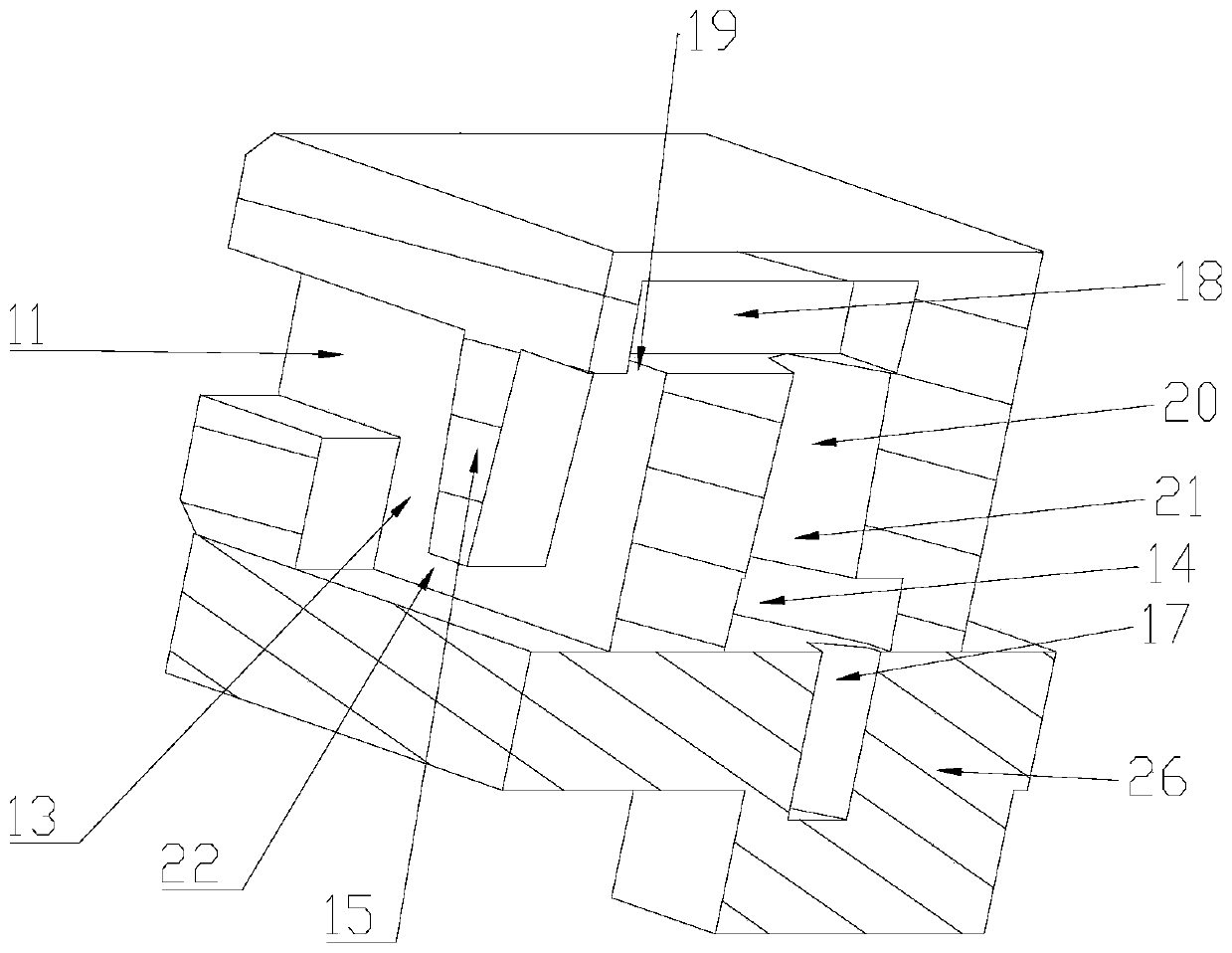
A microphone wind noise preventing apparatus (10) and an electronic device. The apparatus (10) comprises a first sound hole (11), a second sound hole (12), a first cavity (13), a second cavity (14), and a communication channel. The first sound hole (11) and the second sound hole (12) are communicated with each other by means of the first cavity (13). A first flow blocking part opposite to the first sound hole (11) and a second flow blocking part opposite to the second sound hole (12) are provided in the first cavity (13). The communication channel is used for communicating the first cavity (13) with the second cavity (14). The second cavity (14) is communicated with a microphone sound hole (17). An inlet (19) of the communication channel is located between the first flow blocking part and the second flow blocking part. A technical problem to be solved is high wind noise of the existing microphone body. One application of the microphone wind noise preventing apparatus is used for the electronic device.

Description

Technical field [0001] The present invention relates to the technical field of sound energy conversion, and more specifically, to a microphone wind-proof device and electronic equipment using the device. Background technique [0002] The existing headset with a call function is provided with a microphone body in the shell. The sound hole of the microphone body is usually arranged opposite to the sound pickup hole of the housing. [0003] In this case, when the wind blows, it directly blows into the sound hole of the microphone body, resulting in greater wind noise, resulting in a decrease in call quality. Reduce the user experience. Summary of the invention [0004] An object of the present invention is to provide a new technical solution for a microphone wind noise prevention device. [0005] According to the first aspect of the present invention, there is provided a microphone wind-proof device. The device includes a first sound hole, a second sound hole, a first cavity, a secon...

Claims


Application Information

Patent Timeline
Patent Type & Authority Patents(China)
IPC IPC(8): H04R1/08
CPCH04R1/086
Inventor 张献春刘巍
Owner GOERTEK INC
Learn More