
Display device and display method

A display device, three-color technology, applied in light guides, optics, instruments, etc., can solve problems such as limitations, and achieve the effects of reducing cross-color, increasing brightness, and improving contrast.

Active Publication Date: 2017-06-20
BOE TECH GRP CO LTD
View PDF14 Cites 4 Cited by
  • Summary
  • Abstract
  • Description
  • Claims
  • Application Information

AI Technical Summary

Problems solved by technology

[0004] In the prior art, a single sub-pixel electrode corresponds to only one primary color display, such as R or G or B, and the number of pixels per inch (Pixels Per Inch, referred to as: PPI) is limited to a certain extent.

Method used


Image

  • Display device and display method
  • Display device and display method
  • Display device and display method

Examples


Embodiment 1

[0057] Embodiment 1, the light source is a monochromatic light source of at least three colors

[0058] Take a monochromatic light source with three colors as an example, such as Figure 5 As shown, the light source 170 includes a first light source 171, a second light source 172 and a third light source 173, wherein the first light source 171 is a first monochromatic light source, and the second light source 172 is a second monochromatic light source , the third light source 173 is a third monochromatic light source.

[0059] The light guide plate 110 is a three-layer light guide plate, the light incident side of the first layer of light guide plate 111 is provided with a first light source 171, the light incident side of the second layer of light guide plate 112 is provided with a second light source 172, the third layer of light guide plate The light incident side of 113 is provided with a third light source 173 .

[0060] In this embodiment, the first light source 171 , ...

Embodiment 2

[0066] Embodiment 2, the light source is a white light source

[0067] Such as Figure 8 As shown, the light source 170 includes a first light source 171, a second light source 172 and a third light source 173, wherein the first light source 171, the second light source 172 and the third light source 173 are all white light (W )light source.

[0068]The light guide plate 110 is a three-layer light guide plate, the light incident side of the first layer of light guide plate 111 is provided with a first light source 171, the light incident side of the second layer of light guide plate 112 is provided with a second light source 172, the third layer of light guide plate The light incident side of 113 is provided with a third light source 173 .

[0069] Such as Figure 8 and Figure 9 As shown, different light-emitting patterns 160 are provided on each layer of light guide plates, and the first light-emitting patterns 161, second light-emitting patterns 161, and The light-emit...


PUM


Abstract

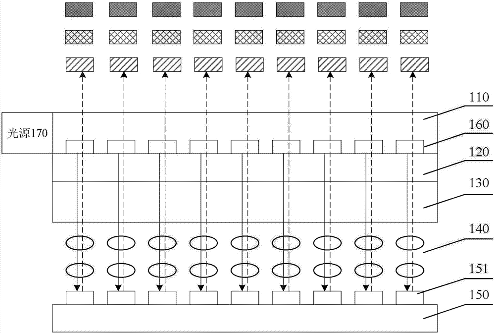
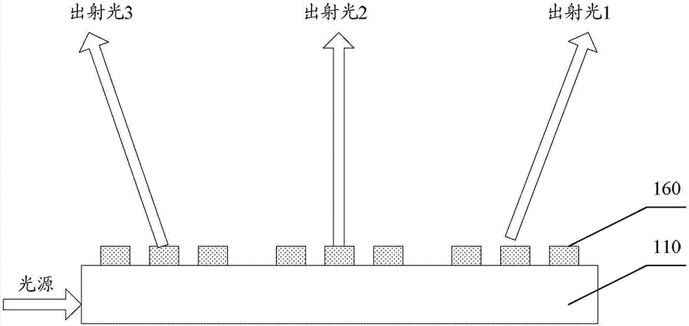
The invention discloses a display device and a display method. The display device includes a light source, a light guide plate, and a liquid crystal panel; the liquid crystal panel includes a first substrate and a second substrate which are oppositely arranged, and a liquid crystal layer is arranged between the first substrate and the second substrate; light emitting graphs are arranged on the light guide plate; incident light of the light source forms at least three colors of monochromatic light beams through the light emitting graphs of the light guide plate; the light source is lighten at different time slots, the at least three colors of monochromatic light beams are irradiated to identical sub pixel electrodes of the first substrate within each frame time at different time slots to form reflective light beams; and the reflective light beams are modulated by the liquid crystal layer and are displayed. In the embodiment of the invention, the light source is lightened at different time slots, the at least three colors of monochromatic light beams are irradiated to identical sub pixel electrodes of the first substrate within each frame time at different time slots, i.e., at least three colors of monochromatic light beams can be displayed at each sub pixel point position, and then the PPI of the display device can be improved.

Description

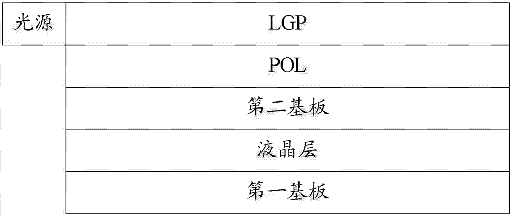
technical field [0001] The present application relates to but not limited to the field of display technology, especially a display device and a display method. Background technique [0002] With the development and upgrading of display technologies, various types of displays appear, including, for example, liquid crystal displays (Liquid Crystal Display, LCD for short). In a display, an optical processing to form a display device with various colors is an important part thereof. [0003] LCD displays generally include reflective LCD displays and transmissive LCD displays. Such as figure 1 As shown, it is a schematic structural diagram of a display device in the prior art. The display device is a reflective display device, and its basic structure generally includes: a first substrate and a second substrate for the box, and a polarizer (Polarizer, referred to as : POL) and light guide panel (Light GuidePanel, referred to as: LGP). Wherein, the first substrate may be a thin...

Claims


Application Information

Patent Timeline
Patent Type & Authority Applications(China)
IPC IPC(8): G02F1/13357G02B6/00
CPCG02B6/0035G02F1/133615G02B6/0036G02B6/0068G02B6/0076G02B6/009G02F1/133621G02F1/133622G02F1/133524G02F1/1336G02F1/1362G02F1/133504G02F1/133553G02F1/133616
Inventor 卢鹏程陈小川杨盛际王磊刘冬妮岳晗付杰肖丽高健李昌峰
Owner BOE TECH GRP CO LTD
Learn More