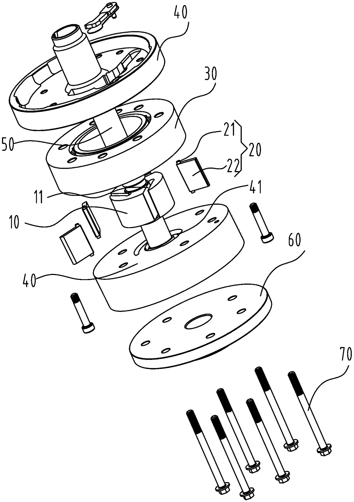
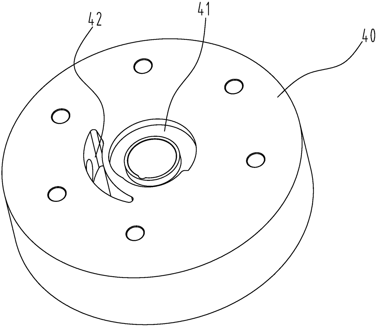
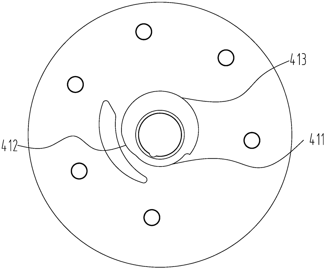
Pump body components, compressors and heat exchange systems

A component and pump body technology, applied in pump elements, liquid fuel engines, components of pumping devices for elastic fluids, etc., to achieve the effects of extending service life, reducing costs, and eliminating frictional power consumption

Active Publication Date: 2018-12-07
GREE ELECTRIC APPLIANCES INC
View PDF6 Cites 0 Cited by
  • Summary
  • Abstract
  • Description
  • Claims
  • Application Information

AI Technical Summary

Problems solved by technology

[0004] The main purpose of the present invention is to provide a pump body assembly, compressor and heat exchange system to solve the problem of friction between the head of the slide vane and the cylinder in the suction stage of the pump body assembly, compressor and heat exchange system in the prior art. The problem of power consumption

Method used


Image

  • Pump body components, compressors and heat exchange systems
  • Pump body components, compressors and heat exchange systems
  • Pump body components, compressors and heat exchange systems

Examples


Embodiment Construction

[0036] It should be noted that, in the case of no conflict, the embodiments in the present application and the features in the embodiments can be combined with each other. The present invention will be described in detail below with reference to the accompanying drawings and examples.

[0037] It should be noted that, unless otherwise specified, all technical and scientific terms used in this application have the same meaning as commonly understood by those of ordinary skill in the art to which this application belongs.

[0038] In the present invention, in the absence of a contrary statement, the used orientation words such as "up and down" usually refer to the direction shown in the drawings, or refer to the vertical, vertical or gravity direction Similarly, for the convenience of understanding and description, "left and right" usually refer to the left and right shown in the drawings; The words are not used to limit the invention.

[0039] In order to solve the problem of...


PUM


Abstract

The invention provides a pump body assembly, a compressor and a heat exchange system. The pump body assembly comprises a roller with a sliding piece groove, a sliding piece, a cylinder and a flange. The sliding piece is arranged at the position of the sliding piece groove in a slidable manner and comprises a first limiting structure. The roller is arranged in the cylinder in a rotatable manner. A second limiting structure is arranged on the surface, facing the roller, of the flange. The first limiting structure and the second limiting structure are used in cooperation so that when the pump body assembly is at the gas suction stage, a gap exists between the head portion of the sliding piece and the inner wall of the cylinder. The pump body assembly, the compressor and the heat exchange system effectively solve the problem that because at the gas suction stage of a pump body assembly, a compressor and a heat exchange system in the prior art, the head portion of the sliding piece makes contact with the cylinder, friction power consumption is generated.

Description

technical field [0001] The invention relates to the technical field of heat exchange, in particular to a pump body assembly, a compressor and a heat exchange system. Background technique [0002] Compared with other types of compressors, the vane compressor has the advantages of simple parts, no eccentric structure, stable torque and small vibration, but at the same time, the vane compressor also has a disadvantage that affects its energy efficiency, that is, the power consumption of the vane head is too big. The sliding vane compressor pushes the vane out of the vane groove through centrifugal force or back pressure of the vane and forms a seal against the inner wall of the cylinder. Due to the large rotation radius of the vane head, the linear velocity is relatively high during operation, causing the vane head to The friction power consumption generated when the head contacts with the cylinder is very large, which is the main source of mechanical power consumption of the ...

Claims


Application Information

Patent Timeline
Patent Type & Authority Patents(China)
IPC IPC(8): F04C18/344F04C29/12F04C29/00
CPCF04C18/3441F04C29/00F04C29/12F04C2240/20
Inventor 罗发游胡余生徐嘉任丽萍万鹏凯吴飞
Owner GREE ELECTRIC APPLIANCES INC
Why Eureka
Try Eureka