Damping mechanism for engine of oil drive rotor-wing unmanned aerial vehicle

A technology of unmanned rotor and aircraft engine, which is applied in the direction of unmanned aircraft, motor vehicles, aircraft parts, etc., can solve problems affecting flight and control effects, and achieve the effect of avoiding unreasonable force and strengthening vibration

Pending Publication Date: 2017-06-20
XIAN TANVEN INTELLIGENT TECH CO LTD
View PDF8 Cites 5 Cited by
  • Summary
  • Abstract
  • Description
  • Claims
  • Application Information

AI Technical Summary

Problems solved by technology

[0004] The purpose of the present invention is to provide a shock absorbing mechanism for the engine of an oil-powered multi-rotor UAV to solve the problem that the body and engine of the current oil-powered multi-rotor UAV resonate and affect the flight and control effects; the invention can improve the performance of the oil-powered multi-rotor Improve the flight performance of drones and improve the safety and stability of drone structures

Method used


Image

  • Damping mechanism for engine of oil drive rotor-wing unmanned aerial vehicle
  • Damping mechanism for engine of oil drive rotor-wing unmanned aerial vehicle

Examples


Embodiment Construction

[0024] In order to make the object, technical solution and advantages of the present invention clearer, the present invention will be further described in detail below in conjunction with the accompanying drawings and implementation examples. It should be understood that the specific examples described here are only used to explain the present invention, not to limit the present invention.

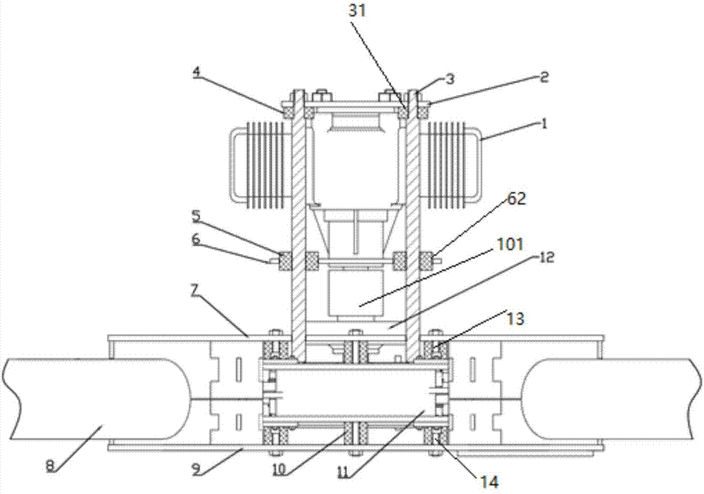
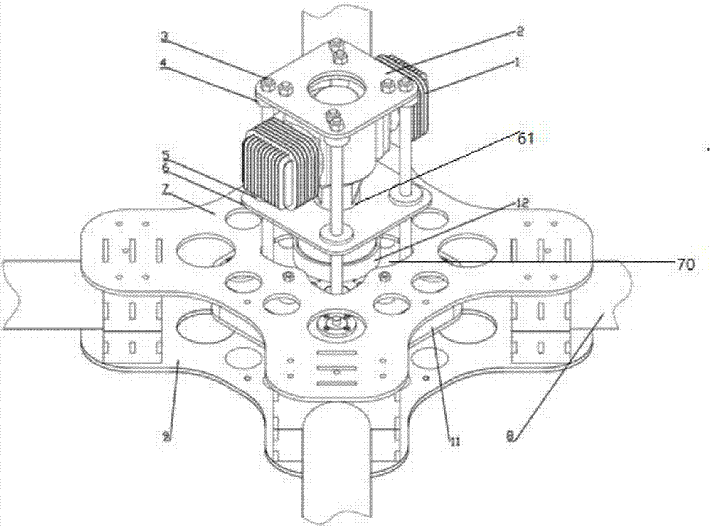
[0025] see figure 1 and figure 2 Shown, the present invention is a kind of engine damping mechanism of oil-operated rotor UAV, including engine installation structure and UAV fuselage.

[0026] The engine mounting structure includes an engine 1, an engine mounting plate 2, several stepped connecting columns 3 and a damping plate 6; a flange 31 is provided on the upper part of the stepped connecting column 3, and an axial Rubber damping pad 4, several stepped connecting columns 3 are connected upwardly to the engine mounting plate 2 through the axial rubber damping pad 4, and are fixedly...


PUM


Abstract

The invention discloses a damping mechanism for an engine of an oil drive rotor-wing unmanned aerial vehicle. The damping mechanism comprises an engine mounting structure and an unmanned aerial vehicle body; the engine mounting structure comprises the engine, an engine mounting plate, a plurality of trapezoidal connecting pillars and a damping plate; the upper portions of upper portion flanges of the trapezoidal connecting pillars are sleeved with axial rubber damping pads, and the multiple trapezoidal connecting pillars are upwards connected with the engine mounting plate through the rubber damping pads; an output shaft of the engine extends out from a through hole in middle of the damping plate; radial damping pads are mounted between the damping plate and the trapezoidal connecting pillars; a gear reduction box is connected to the unmanned aerial vehicle body through a plurality of flexible rubber damping pads; the output shaft of the engine is connected with the input end of the gear reduction box through a clutch; and the lower ends of the multiple trapezoidal connecting pillars are connected to an outer shell of the gear reduction box in a rigidity mode. According to the damping mechanism for the engine of the oil drive rotor-wing unmanned aerial vehicle, the problem that the flying and controlling effects are influenced by resonance of a current oil drive multi-rotor-wing unmanned aerial vehicle body and the engine is solved; and flying performance and safe stability of the oil drive multi-rotor-wing unmanned aerial vehicle can be promoted.

Description

technical field [0001] The invention belongs to the field of oil-operated rotor drones, and in particular relates to an engine damping mechanism of an oil-operated rotor drone. Background technique [0002] In recent years, the UAV industry has developed rapidly. Oil-powered UAVs have been vigorously developed in the industry because they are fuel-powered and do not need to be restricted by batteries like electric UAVs. However, because the engine used by the oil-powered UAV is always in a state of vibration in the working state, this vibration is transmitted to all parts of the UAV through the fuselage, which is very unfavorable for the work of the UAV, and affects flight stability at least. , and damage the body structure in severe cases. It even caused the drone to disintegrate during flight. For the single-cylinder or double-cylinder piston engines used by most oil-powered drones at present, the vibration in the working state is more severe. Therefore, it is necessary...

Claims


Application Information

Patent Timeline
Patent Type & Authority Applications(China)
IPC IPC(8): B64D27/26B64D27/40
CPCB64U50/11B64U10/10B64D27/40
Inventor 程靖王新升刘喜龙左盘飞吕京兆
Owner XIAN TANVEN INTELLIGENT TECH CO LTD
Why Eureka
Try Eureka