
a welding device

A welding equipment and assembly technology, applied in the direction of welding equipment, auxiliary welding equipment, welding/cutting auxiliary equipment, etc., can solve problems such as unsafety, troublesome ropes, and dangerous operation, so as to reduce potential safety hazards, facilitate use, and prevent The effect of reverse rotation

Active Publication Date: 2018-07-03
晖腾工业科技有限公司
View PDF6 Cites 0 Cited by
  • Summary
  • Abstract
  • Description
  • Claims
  • Application Information

AI Technical Summary

Problems solved by technology

[0002] Nowadays, welding technology is widely used, and welding locations can be seen everywhere. There are workpieces welded in workshops, and buildings are welded at high altitudes, such as house steel frames, bridge iron frames, etc. High-altitude welding operations are dangerous, so it is necessary to Welders add safety belts to ensure safety. The existing safety belts are usually composed of simple ropes. When the welding position needs to be adjusted, it is troublesome to manually adjust the length of the ropes, and it is not safe.

Method used


Image

  • a welding device
  • a welding device
  • a welding device

Examples


Embodiment Construction

[0017] All features disclosed in this specification, or steps in all methods or processes disclosed, may be combined in any manner, except for mutually exclusive features and / or steps.

[0018] Any feature disclosed in this specification (including any appended claims, abstract and drawings), unless expressly stated otherwise, may be replaced by alternative features which are equivalent or serve a similar purpose. That is, unless expressly stated otherwise, each feature is one example only of a series of equivalent or similar features.

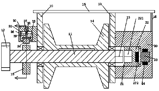
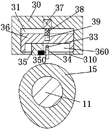
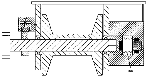
[0019] Such as Figure 1-4 As shown, a welding device of the present invention includes a mounting base frame 10, a rotating shaft 11 rotatably installed in the mounting base frame 10 through a bearing, and a safety device fixedly installed on the rotating shaft 11. Belt cylinder 14, the left end of the rotating shaft 11 is fixedly equipped with a drive toothed wheel 12, and the right end of the installation base 10 is installed with a revers...


PUM


Abstract

Welding equipment comprises an installing base frame, a rotary shaft rotationally installed in the installing base frame through a bearing, and a safety belt barrel fixedly installed on the rotary shaft, wherein a driving gear is fixedly installed at the left end of the rotary shaft; a reverse rotation limiting device is installed at the right end of the installing base frame and comprises a right connecting frame fixedly installed on the right end surface of the installing base frame; a sliding groove with the open end facing the rotary shaft is formed in the right connecting frame and internally provided with a sliding block in a sliding mode; a magnet bar is fixedly installed in the right end surface of the sliding block; an iron bar is fixedly installed in the right end wall of the sliding groove; an inductor is fixedly installed on the outer circle of the iron bar; a transverse beam rod is fixedly installed on the upper side of the installing base frame; a right reinforcement rod is fixedly installed on the right side of the transverse beam rod and used for reinforcing the right connecting frame; and a reverse rotation sensing device is installed at the left end of the installing base frame.

Description

technical field [0001] The invention relates to the field of welding equipment, in particular to high-altitude welding protection equipment. Background technique [0002] Nowadays, welding technology is widely used, and welding locations can be seen everywhere. There are workpieces welded in workshops, and buildings are welded at high altitudes, such as house steel frames, bridge iron frames, etc. High-altitude welding operations are dangerous, so it is necessary to Welders add safety belts to ensure safety. The existing safety belts usually consist of simple ropes. When the welding position needs to be adjusted, manual adjustment of the length of the ropes is cumbersome and unsafe. Contents of the invention [0003] The object of the present invention is to provide a welding device and its use method, which can overcome the above-mentioned defects of the prior art. [0004] According to the present invention, a welding device of the device of the present invention includ...

Claims


Application Information

Patent Timeline
Patent Type & Authority Patents(China)
IPC IPC(8): B23K37/00
CPCB23K37/00B23K37/006
Inventor 欧阳翎
Owner 晖腾工业科技有限公司
Learn More