
One-way vibration system, device and method based on linear motors

A linear motor and vibration system technology, applied in the direction of linear DC motor control, control system, AC motor control, etc., can solve the problems of limiting the application field of the motor and the single vibration effect of the motor, and achieve the effect of increasing the application field

Active Publication Date: 2017-06-13
TRULY OPTO ELECTRONICS
View PDF4 Cites 3 Cited by
  • Summary
  • Abstract
  • Description
  • Claims
  • Application Information

AI Technical Summary

Problems solved by technology

[0003] At present, the motor vibration effect on the market is relatively single and simple, and the traditional symmetrical vibration effect is mostly used, which limits the application field of the motor to a certain extent.

Method used


Image

  • One-way vibration system, device and method based on linear motors
  • One-way vibration system, device and method based on linear motors
  • One-way vibration system, device and method based on linear motors

Examples


Embodiment 1

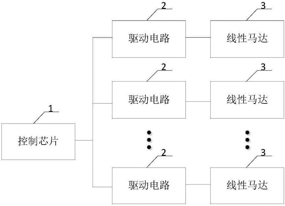
[0038] Please refer to figure 2 , figure 2 A structural schematic diagram of a unidirectional vibration system based on a linear motor provided by the present invention, the system includes:

[0039] A plurality of linear motors 3, wherein the resonance frequencies of any two linear motors 3 differ by an integer multiple;

[0040] Specifically, in order to realize that the vibrations of the multiple linear motors 3 can achieve the effect of unidirectional vibration after synthesis, it is required that the resonance frequencies of any two linear motors 3 in the multiple linear motors 3 differ by an integer multiple, for example, can be 2 times . Of course, the integer multiples and the specific resonance frequency values ​​of the multiple linear motors 3 are not particularly limited here, and they are determined according to actual conditions.

[0041] The control chip 1 is configured to output drive signals corresponding to each linear motor 3 one-to-one according to a first user ...

Embodiment 2

[0053] Please refer to Figure 4 , Figure 4 This is a schematic structural diagram of another one-way vibration system based on a linear motor provided by the present invention.

[0054] The system is based on the above embodiments:

[0055] Preferably, the number of linear motors is two, namely the first linear motor 31 and the second linear motor 32, and the two drive signals respectively correspond to the first drive signal and the second drive signal, and the two drive circuits respectively Corresponding to the first driving circuit 21 and the second driving circuit 22.


PUM


Abstract

The invention discloses a one-way vibration system, device and method based on linear motors. The system comprises the multiple linear motors, a control chip and driving circuits, wherein the resonant frequencies between any two linear motors differ in integral multiple, the control chip is used for outputting driving signals corresponding to the linear motors one to one according to a first user instruction, the frequency of each driving signal is within the preset range by adopting the resonant frequency of the corresponding linear motor as the reference, and any two driving signals have phase angles with adjustable phases; the driving circuits correspond to the linear motors one to one and are used for driving and amplifying the driving signals, and sending the driven and amplified driving signals to the corresponding linear motors so as to control the corresponding linear motors, and then the one-way vibration effect is obtained. It is thus clear that the vibration effects of the multiple linear motors can be equivalent to one-way vibration after being synthesized, and the application range is enlarged.

Description

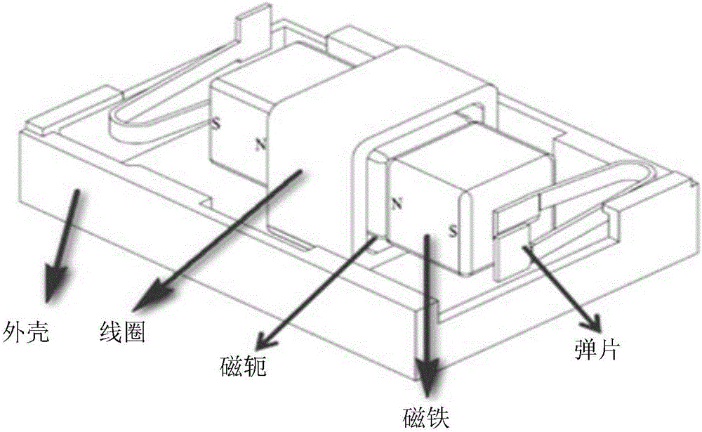
Technical field [0001] The present invention relates to the technical field of motor vibration, in particular to a one-way one-way vibration system, device and method based on a linear motor. Background technique [0002] Linear motors are used in many fields, please refer to figure 1 , figure 1 It is a schematic diagram of the linear motor structure. The linear motor includes a yoke for connecting magnets of the same nature, an elastic sheet for generating a restoring force due to the compression of the vibrator when the vibrator moves to both ends, and a magnet for moving under the action of the magnetic field of the coil , It is used to generate a magnetic field with a change of direction after the alternating current is applied to drive the coil of the magnet to move and the shell for protection and shielding. When the alternating current is passed through the coil, due to the change of the current polarity, the coil will produce a magnetic field with a direction change. The ...

Claims


Application Information

Patent Timeline
IPC IPC(8): H02P5/00H02P7/02H02P25/06H02P25/032
CPCH02P5/00H02P7/00H02P25/06
Inventor 周雷王治玺
Owner TRULY OPTO ELECTRONICS
Learn More