
Double-rotor motor with permanent magnet-magnetic resistance axial magnetic flux composite structure

A dual-rotor motor and axial flux technology, applied in the direction of magnetic circuit shape/style/structure, magnetic circuit rotating parts, magnetic circuit, etc., can solve the problem of motor performance, large cogging torque, and electromagnetic problems that affect system control accuracy. Noise and other problems, to achieve the effect of improving work efficiency and power density, large output torque, and high operating speed

Inactive Publication Date: 2017-06-13
CHONGQING UNIV
View PDF4 Cites 6 Cited by
  • Summary
  • Abstract
  • Description
  • Claims
  • Application Information

AI Technical Summary

Problems solved by technology

[0004] The tendency that the facing area of ​​the intermediate rotor teeth and the stator teeth is constant leads to the cogging torque of the axial magnetic flux switching permanent magnet motor is larger than that of the traditional permanent magnet motor, and the cogging torque tries to make the intermediate rotor of the motor return to its original position. Therefore, the axial magnetic flux switching permanent magnet motor has problems such as large vibration, large electromagnetic noise, and difficulty in starting during operation, which affect the control accuracy of the system and the performance of the motor.

Method used


Image

  • Double-rotor motor with permanent magnet-magnetic resistance axial magnetic flux composite structure
  • Double-rotor motor with permanent magnet-magnetic resistance axial magnetic flux composite structure

Examples


Embodiment Construction

[0016] Below in conjunction with accompanying drawing and embodiment the present invention will be further described:

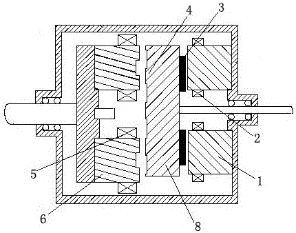
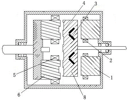
[0017] like figure 1 As shown, the present invention includes a stator 1, a first rotor 8, and a second rotor 6 arranged axially. The inner end surface of the stator 1 is a circular surface, and slots are radially divergent on the inner end surface of the stator, and three phases are placed in the slots. Distributed armature winding 2; permanent magnets 3 are installed on the side facing the stator of the first rotor 8, and the permanent magnets 3 are evenly distributed on the circular surface, and the first rotor 8 is provided with a circumferential distribution The salient pole 4; the inner end surface of the second rotor 6 diverges in the radial direction and slots, and the three-phase concentrated winding 5 is placed in the slots.

[0018] figure 1 In the illustrated embodiment, the permanent magnets 3 are arranged on the axially outer end surface of th...


PUM


Abstract

The invention discloses a double-rotor motor with a permanent magnet-magnetic resistance axial magnetic flux composite structure. The double-rotor motor comprises stators (1), a first rotor (8) and a second rotor (6), wherein the stators (1) are arranged in an axial direction; the inner end surface of each stator (1) is a circular surface, grooves are distributed at the inner end surface of each stator in the radial direction, and three-phase distributed type armature windings (2) are arranged in the grooves; permanent magnets (3) are arranged at the end surface, facing the stators, of the first rotor (8), and are uniformly distributed at the circular surface; the end surface, facing the second rotor (6), of the first rotor (8) is provided with convex poles (4) which are distributed along the circumference; grooves are distributed at the inner end surface of the second rotor (6) in the radial direction, and three-phase centralized type windings (5) are arranged in the grooves. The double-rotor motor has the beneficial effects that the toothed groove torque of the system is weakened, and the vibration and electromagnetic noise are decreased; the power density and power factor of the system are improved, and the transfer efficiency is improved; the electromagnetic torque of the system is improved, and the driving force of a hybrid automobile is improved.

Description

technical field [0001] The invention belongs to the field of hybrid electric vehicles, and in particular relates to a permanent magnet-reluctance axial flux composite structure double-rotor motor used for a hybrid electric vehicle. Background technique [0002] The hybrid electric vehicle drive system uses an axial field flux-switching permanent magnet motor. "Analysis of Cogging Torque of Axial Magnetic Flux Switching Permanent Magnet Motor", Lin Mingyao et al., Journal of Electrical Machinery and Control, Vol. 13, No. 6, pp. 787-791, November 2009 recorded an axial magnetic field Flux switching permanent magnet motor, the motor is the first stator, intermediate rotor and second stator from left to right, each stator is composed of 12 "U"-shaped magnetic cores, 12 coils and 12 permanent magnets , each coil is wound on the teeth of two adjacent U”-shaped magnetic permeable cores, with permanent magnets embedded in the middle, the permanent magnets are alternately magnetized...

Claims


Application Information

Patent Timeline
Patent Type & Authority Applications(China)
IPC IPC(8): H02K16/02H02K1/27H02K1/24H02K1/16
CPCH02K16/02H02K1/165H02K1/24H02K1/2793H02K2201/03
Inventor 徐奇伟孙静赵蒙蒋小彪罗骁枭毛韫琦陈伟东刘旭王志远
Owner CHONGQING UNIV
Learn More