Adsorption rod, vacuum laminating equipment and control method of vacuum laminating equipment

A control method and adsorption rod technology, which are applied in the directions of electromagnets with armatures, electromagnets without armatures, instruments, etc., can solve problems such as the inability of the adsorption rods to adjust their own lengths.

Inactive Publication Date: 2017-06-13
HEFEI XINSHENG OPTOELECTRONICS TECH CO LTD +1
View PDF6 Cites 6 Cited by
  • Summary
  • Abstract
  • Description
  • Claims
  • Application Information

AI Technical Summary

Problems solved by technology

[0007] The embodiment of the present invention provides an adsorption rod, vacuum lamination equipment, and a control method for vacuum lamination equipment, which can solve the problem that the adsorption rod cannot adjust its own length in the vacuum lamination equipment

Method used


Image

  • Adsorption rod, vacuum laminating equipment and control method of vacuum laminating equipment
  • Adsorption rod, vacuum laminating equipment and control method of vacuum laminating equipment
  • Adsorption rod, vacuum laminating equipment and control method of vacuum laminating equipment

Examples


Embodiment Construction

[0038] The following will clearly and completely describe the technical solutions in the embodiments of the present invention with reference to the accompanying drawings in the embodiments of the present invention. Obviously, the described embodiments are only some, not all, embodiments of the present invention. Based on the embodiments of the present invention, all other embodiments obtained by persons of ordinary skill in the art without making creative efforts belong to the protection scope of the present invention.

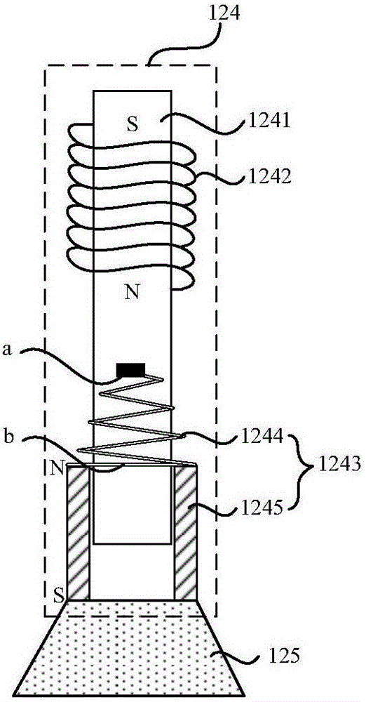
[0039] An embodiment of the present invention provides an adsorption rod, such as image 3 As shown, it includes an electromagnetic assembly 124, the electromagnetic assembly 124 includes a slide bar 1241, and a fixed coil 1242 and a movable part 1243 arranged on the slide bar 1241, the fixed coil 1242 is wound around the outer periphery of the slide bar 1241, and the movable part 1243 includes an elastic element 1244 and a movable part 1243. The movable magne...


PUM


Abstract

An embodiment of the invention provides an adsorption rod, vacuum laminating equipment and a control method of the vacuum laminating equipment, relates to the technical field of display panel manufacturing and can solve the problem that adsorption rods of vacuum laminating equipment cannot adjust the self-height. The adsorption rod comprises an electromagnetic assembly and an adsorption part, wherein the electromagnetic assembly comprises a slide bar as well as a fixed coil and a movable part which are arranged on the slide bar, the fixed coil winds around the periphery of the slide bar, the movable part comprises an elastic element and a movable magnet, a fixed end of the elastic element is fixedly connected with the slide rod, and a movable end of the elastic element is connected with the movable magnet; the adsorption part is fixedly connected with the movable magnet and exposed out of one end, far away from the fixed coil, of the movable magnet. Current passes through the fixed coil to produce a magnetic field, so that the movable magnet slides on the slide bar under the repulsive force action of the magnetic field.

Description

technical field [0001] The invention relates to the technical field of display panel manufacturing, in particular to an adsorption rod, vacuum lamination equipment and a control method for the vacuum lamination equipment. Background technique [0002] In the TFT-LCD (Thin Film Transistor-Liquid Crystal Display, thin film field effect transistor liquid crystal display) manufacturing industry, the vacuum lamination process refers to that in a closed vacuum environment, the vacuum lamination equipment (Vacuum Aligner System, VAS for short) The upper base and the lower base in ) absorb the color filter substrate and the array substrate respectively, and through the relative movement between the upper base and the lower base, align and bond the color filter substrate and the array substrate to form a liquid crystal panel. [0003] Such as figure 1 As shown, the existing vacuum lamination equipment usually includes an upper chamber 10 and a lower chamber 20 arranged opposite to e...

Claims


Application Information

Patent Timeline
Patent Type & Authority Applications(China)
IPC IPC(8): G02F1/13
CPCG02F1/1303G02F1/1341H01F7/13H01F7/1646H01F2007/1866H01F7/20G02F1/133516
Inventor 侯本象唐大虎谢军
Owner HEFEI XINSHENG OPTOELECTRONICS TECH CO LTD
Why Eureka
Try Eureka