
Gear case lubricating oil automatic adding device

A technology of automatic adding and gearbox, which is applied in the direction of gear lubrication/cooling, transmission parts, belt/chain/gear, etc., which can solve the hidden dangers of mechanical equipment failure, lack of lubricating oil, and affect the working efficiency of mechanical equipment, etc., to avoid Increased temperature and wear, automatic oiling and lubrication, and shortened downtime for maintenance

Pending Publication Date: 2017-06-13
CHONGQING YINCONG TECH CO LTD
View PDF11 Cites 6 Cited by
  • Summary
  • Abstract
  • Description
  • Claims
  • Application Information

AI Technical Summary

Problems solved by technology

[0002] The gearbox is an important mechanical part in the transmission mechanism. It is inevitable that there will be a lack of lubricating oil after long-term operation. At this time, continuing to run at this time will affect the working efficiency of the mechanical equipment. During the operation of the gearbox, the lack of lubricating oil will cause The transmission resistance between the gears increases, causing the temperature of the gears to rise, accelerating the wear of the gears, and the long-term high-temperature operation will easily cause fatigue effects on the metal, which will bring potential hidden dangers to mechanical equipment.
The lubricating oil not only plays a lubricating role, but also avoids high temperature when the gear is working. The traditional gear lubricating oil is often added manually, which is inconvenient when there are many mechanical parts or the equipment structure is complex. and time consuming

Method used


Image

  • Gear case lubricating oil automatic adding device
  • Gear case lubricating oil automatic adding device

Examples


Embodiment Construction

[0012] The following will clearly and completely describe the technical solutions in the embodiments of the present invention with reference to the accompanying drawings in the embodiments of the present invention. Obviously, the described embodiments are only some, not all, embodiments of the present invention. Based on the embodiments of the present invention, all other embodiments obtained by persons of ordinary skill in the art without making creative efforts belong to the protection scope of the present invention.

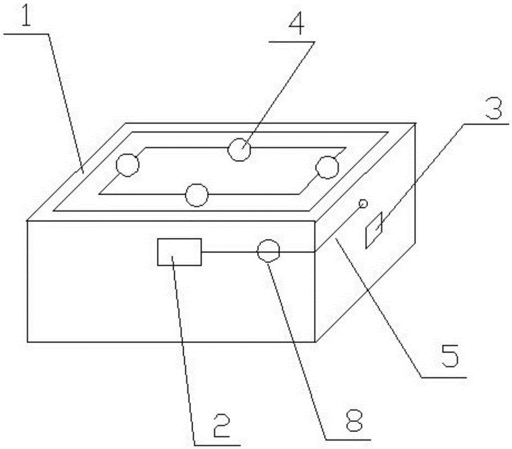
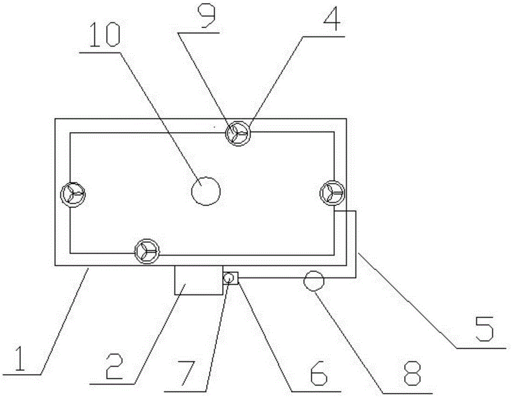
[0013] see figure 1 and 2 , an automatic adding device for gearbox lubricating oil, comprising an oil storage chamber 2 arranged on the outer wall of the gearbox casing 1, a controller 3 and an oil injection head 4 arranged on the inner wall of the gearbox casing 1, the oil injection Oil outlet holes are evenly distributed on the surface of the head 4. The oil injection head 4 is connected to the output port 6 provided on the side wall of the oil storage cham...


PUM


Abstract

The invention discloses a gear case lubricating oil automatic adding device. The gear case lubricating oil automatic adding device comprises an oil storage chamber arranged on the outer side wall of a gear case body, a controller and an oil spraying head arranged on the inner side wall of the gear case body; the oil spraying head is connected to an output opening formed in the side wall of the oil storage chamber through a conveying pipe transversely penetrating the side wall of the case body, an electric control gate is arranged on the output opening, and a flowmeter is connected to the middle portion of the conveying pipe; a turbine mechanism is arranged in the oil spraying head, a voice frequency detecting device is arranged on the inner wall of the upper surface of the case body, and a comparison device is arranged inside the controller; and the electric control gate, the flowmeter, the turbine mechanism and the voice frequency detecting device are all electrically connected with the controller. According to the device, abnormal gear running sounds in a gear case are detected through the voice frequency detecting device, the controller controls to open the electric control gate and run the turbine mechanism, lubricating oil is sprayed to gears to achieve automatic lubricating oil adding and lubricating, time and labor are saved, the mechanical equipment halting maintaining time can be shortened, the structure is simple, and popularization is easy.

Description

technical field [0001] The invention relates to a maintenance device for mechanical parts, in particular to an automatic lubricating oil adding device for a gearbox, and belongs to the technical field of mechanical lubrication equipment. Background technique [0002] The gearbox is an important mechanical part in the transmission mechanism. It is inevitable that there will be a lack of lubricating oil after long-term operation. At this time, continuing to run at this time will affect the working efficiency of the mechanical equipment. During the operation of the gearbox, the lack of lubricating oil will cause The transmission resistance between the gears increases, causing the temperature of the gears to rise, accelerating the wear of the gears, and the long-term high-temperature operation will easily cause fatigue effects on the metal, which will bring potential hidden dangers to mechanical equipment. The lubricating oil not only plays a lubricating role, but also avoids hi...

Claims


Application Information

Patent Timeline
IPC IPC(8): F16H57/04
CPCF16H57/0434F16H57/0456
Inventor 雷登银
Owner CHONGQING YINCONG TECH CO LTD
Learn More