
Pressure cylinder having motion sleeve, in paticular to active cylinder

A pressure cylinder and pressure chamber technology, applied in the field of pressure cylinders, can solve problems such as uncomfortable noise and achieve the effect of simple assembly

Active Publication Date: 2017-06-13
SCHAEFFLER TECH AG & CO KG
View PDF5 Cites 6 Cited by
  • Summary
  • Abstract
  • Description
  • Claims
  • Application Information

AI Technical Summary

Problems solved by technology

Wear of the seals can in turn lead to unpleasant noises due to the fluid flow that occurs in the so-called "ventilated state", that is to say in the case of pressure chambers that are open towards the side channels

Method used


Image

  • Pressure cylinder having motion sleeve, in paticular to active cylinder
  • Pressure cylinder having motion sleeve, in paticular to active cylinder
  • Pressure cylinder having motion sleeve, in paticular to active cylinder

Examples


Embodiment Construction

[0054] These figures are only schematic in nature and are only used for the understanding of the invention. The same elements are provided with the same reference numerals. The features of the individual embodiments can be freely combined with each other without departing from the core idea of ​​the invention.

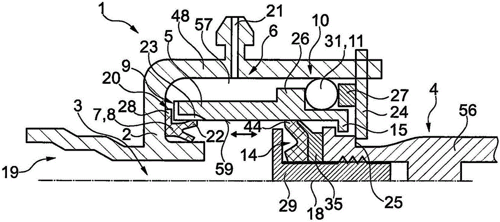
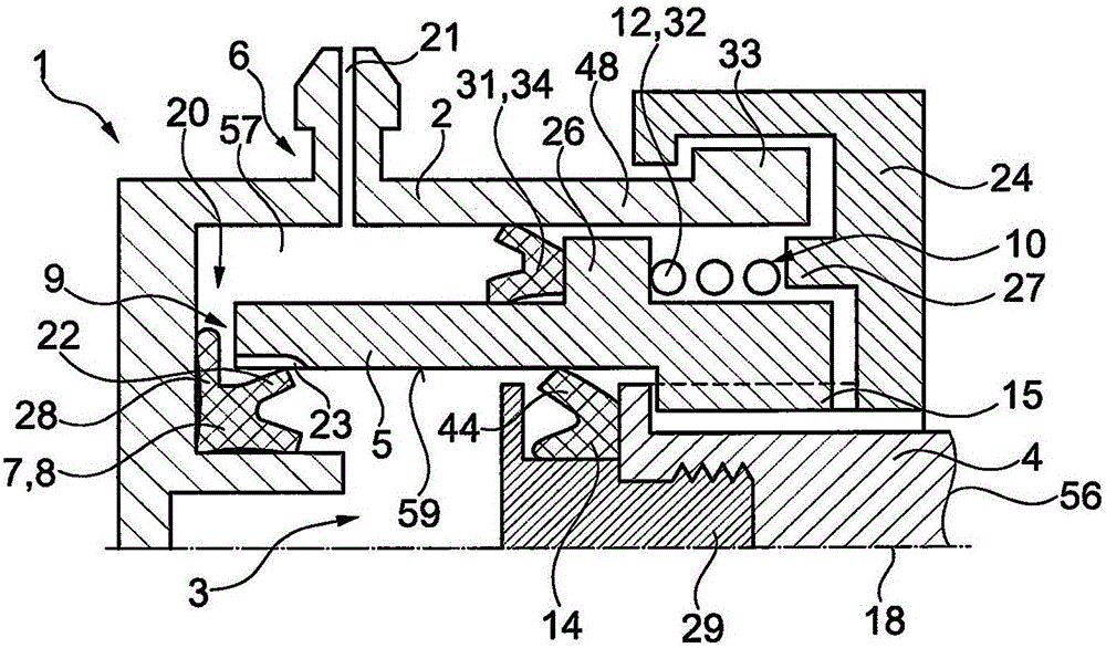
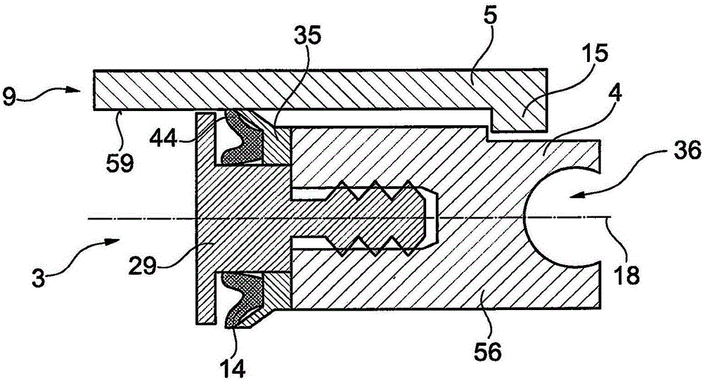
[0055] figure 1 A first embodiment of a pressure cylinder 1 according to the invention is firstly shown in . As long as it is not stated otherwise, the rest of the subsequently described exemplary embodiments correspond in construction and function to this first exemplary embodiment.

[0056] The pressure cylinder 1 is realized as a master cylinder of an actuating device for actuating a clutch of a motor vehicle. Correspondingly, the pressure cylinder 1 is used in the usual manner as a fluid pressure-generating element which can be actuated, for example, via a clutch pedal and which is fluidly connected to a slave cylinder of an actuating device in order to actuate ...


PUM


Abstract

The invention relates to a pressure cylinder (1) for actuating a clutch of a motor vehicle drive train, comprising a housing (2), a pressure piston (4) which is movably mounted in said housing (2) and forms a fluidic pressure chamber (3) with the housing (2) (5) guide sleeve which is accommodated in the housing (2) and is designed to guide the pressure piston (4) in at least one partial section of its displacement path, the guide sleeve (5) being displaceable relative to the housing (2) in such a way that thepressure chamber (3) is fluidically connected to a side channel (6) which can be connected to a fluid reservoir in an opening position of the guide sleeve (5) and is fluidically separated from the side channel (6) in a closed position of the guide sleeve (5); and the invention also relates to a clutch for a drive train with such a pressure cylinder (1).

Description

technical field [0001] The invention relates to a pressure cylinder, which is preferably designed as a master cylinder, for actuating a clutch of a drive train of a motor vehicle, that is to say like a motor vehicle, truck, utility vehicle or In the drive of a motor vehicle such as an agricultural commercial vehicle, the clutch is, for example, a friction clutch, and the pressure cylinder has: a housing; a pressure piston constituting a fluid pressure chamber; and a guide sleeve received in the housing, the guide sleeve being in at least a partial section of the movement path of the pressure piston (preferably in the The entire movement path) is configured for guiding the pressure piston. Background technique [0002] Such active cylinders / pressure cylinders are already known from the prior art. In this context, for example DE 10 2005 004 195 A1 discloses a master cylinder for a hydraulic actuation system with a housing and an axially displaceable piston in the housing, wh...

Claims


Application Information

Patent Timeline
Patent Type & Authority Applications(China)
IPC IPC(8): F15B7/08B60K23/02F15B15/14
CPCB60K23/02F15B7/08F15B15/1423F15B15/1452F16D25/08F16D25/088F16D2025/081
Inventor P·瓦格纳
Owner SCHAEFFLER TECH AG & CO KG
Learn More