Padlock

A technology for padlocks and lock levers, applied in the field of locks, which can solve problems such as motor jamming and control of the rotation range of the locking part

Inactive Publication Date: 2017-06-13
ZHEJIANG PUJIANG PLUM BLOSSOM LOCK IND GROUP
View PDF4 Cites 7 Cited by
  • Summary
  • Abstract
  • Description
  • Claims
  • Application Information

AI Technical Summary

Problems solved by technology

Another existing padlock needs to be provided with a limit mechanism to lock the motor to control the rotation range of the locking part

Method used


Image

  • Padlock
  • Padlock
  • Padlock

Examples


Embodiment Construction

[0027] In order to further illustrate the technical means and effects of the present invention to achieve the intended purpose of the invention, the specific implementation, structure, features, and effects of the present invention will be described in detail below with reference to the drawings and preferred embodiments.

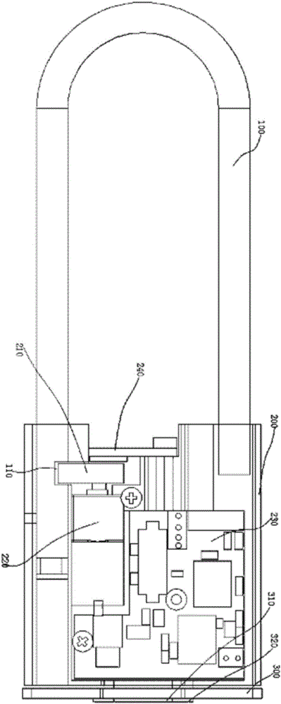
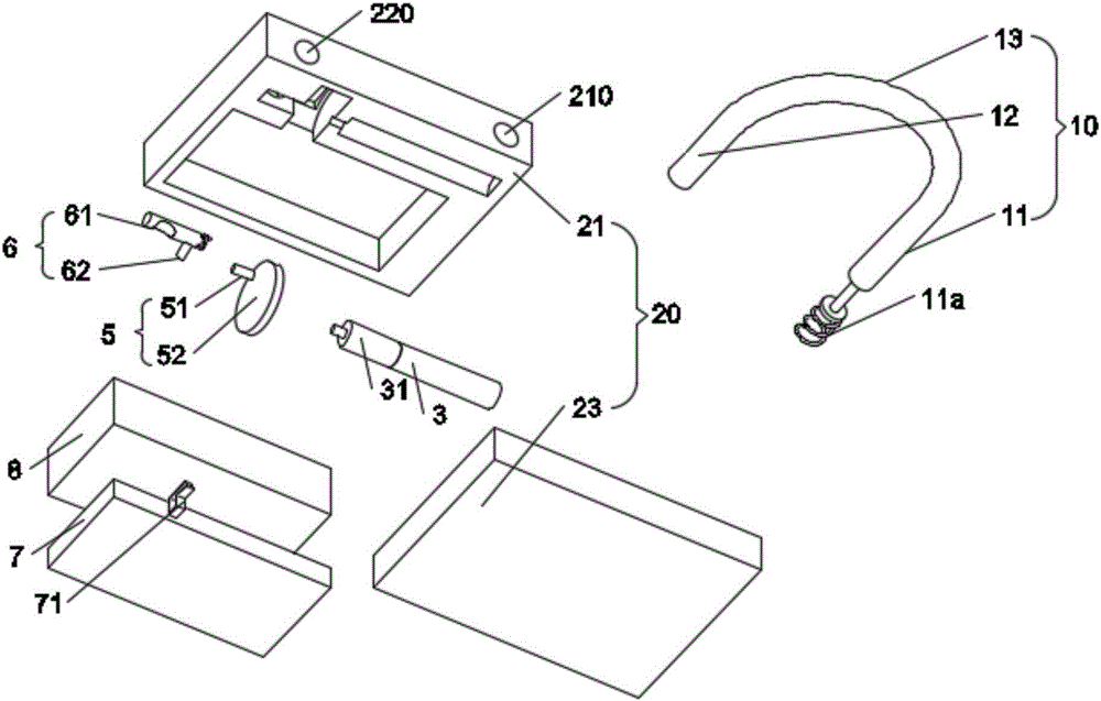
[0028] figure 2 Shown is a structural diagram of the locked state of the padlock according to the first embodiment of the present invention. See figure 2 , The padlock of the first embodiment of the present invention includes a U-shaped lock beam 10 and a lock body 20.

[0029] The lock beam 10 includes a long lock rod 11, a short lock rod 12, and a U-shaped connecting rod 13 connecting the long lock rod 11 and the short lock rod 12.

[0030] image 3 Shown as figure 2 Exploded view of padlock. See image 3 , The lock body 20 includes a first lock shell 21 and a second lock shell 22. The lock body 20 contains a motor 3, a toggle part 5, a locking part 6, a ci...


PUM


Abstract

The invention provides a padlock. The padlock comprises a locking portion and is characterized in that the locking portion comprises a cylindrical rotary column and a transmission rod fixedly connected with the rotary column, the rotary column is adjacent to the middles/middle of a long blind hole and/or a short blind hole, a motor is adjacent to the middle of the long blind hole or the short blind hole, the motor and the rotary column are located on two sides of the long blind hole and the short blind hole respectively, unlocking recesses are formed in the positions, corresponding to a long lock rod and/or short lock rod, of the rotary column, matching recesses are formed in one sides, facing the rotary column, of the long lock rod and/or the short lock rod, a shifting portion is fixed at the output end of the motor and used for shifting the transmission rod to allow the rotary column to rotate, and a torsional spring for keeping protruding portions, opposite to the unlocking recesses, of the rotary column being accommodated in the matching recesses is arranged between the rotary column and a lock body. When the protruding portions are accommodated in the matching recesses, the locking portion locks a lock beam; when the unlocking recesses face the matching recesses, the locking portion unlocks the lock beam, and the transmission rod is tangential to the rotation trajectory of the edge of the shifting portion when the unlocking recesses face the matching recesses.

Description

Technical field [0001] The invention relates to the field of locks, in particular to a padlock. Background technique [0002] Today’s lock technology has developed an electronic lock cylinder that uses electricity to operate. This electronic lock cylinder is commonly used in the current society. For example, electronic lock cylinders are often used as door locks for doors, car locks for automobiles, or safe boxes. lock. The lock cylinder is the most important component of the lock, and most of the actions of opening and locking the lock are completed by the lock cylinder. [0003] figure 1 Shown is a schematic structural diagram of an existing padlock. See figure 1 The document with the authorization announcement number CN205531813U discloses an electronic padlock including a lock lever 100 and a lock body 200. The lock body 200 is provided with a bolt 210 (unlocking part), a drive motor 220 and a control board 230. The driving motor 220 is connected to the lock tongue 210, whic...

Claims


Application Information

Patent Timeline
Patent Type & Authority Applications(China)
IPC IPC(8): E05B47/00E05B49/00E05B67/22
CPCE05B47/0012E05B49/00E05B67/22E05B2047/0017E05B2047/0048
Inventor 张福禄
Owner ZHEJIANG PUJIANG PLUM BLOSSOM LOCK IND GROUP
Why Eureka
Try Eureka