Electronic component conveying apparatus and electronic component inspection apparatus
A technology for electronic components and conveying devices, used in conveyors, measuring devices, mechanical conveyors, etc.
- Summary
- Abstract
- Description
- Claims
- Application Information
AI Technical Summary
Problems solved by technology
Method used
Image
Examples
no. 1 approach
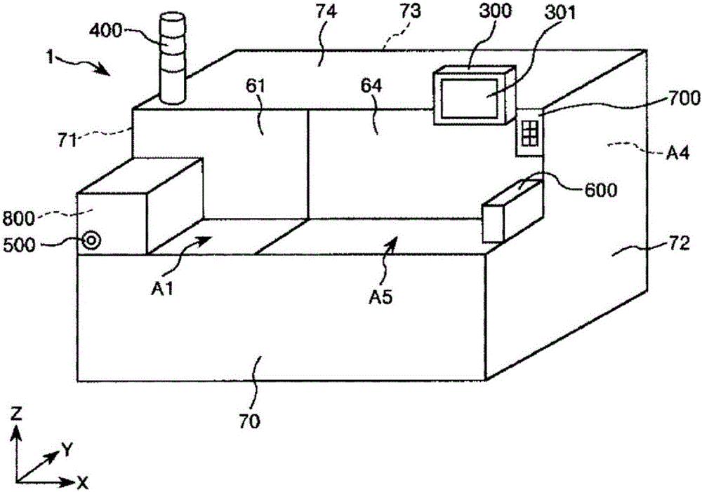
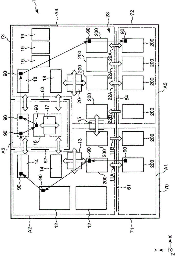
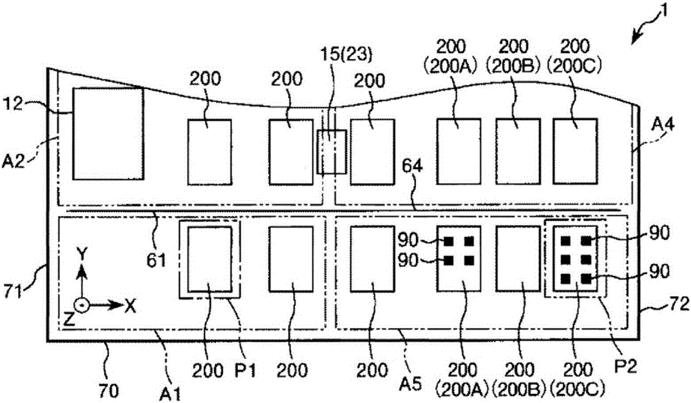
[0181] figure 1 It is a schematic perspective view which looked at 1st Embodiment of the electronic component inspection apparatus of this invention from the front side. figure 2 yes means figure 1 It is a schematic plan view of the normal operation state of the electronic component inspection apparatus shown. Figure 3 ~ Figure 8 respectively in order figure 1 A schematic plan view of the retest operation state of the electronic component inspection apparatus shown. Figure 12 to Figure 14 respectively in figure 1 An example of an operation screen used for setting the retest operation of the electronic component inspection apparatus shown is shown. Figure 15 is in figure 1 An example of an operation panel used for setting the retest operation of the electronic component inspection apparatus shown is shown.
[0182] Hereinafter, a first embodiment of an electronic component conveying device and an electronic component inspection device according to the present inventio...
no. 2 approach
[0248] Figure 9 It is a schematic plan view sequentially showing the retest operation state of the electronic component inspection device (second embodiment) of the present invention.
[0249] Hereinafter, a second embodiment of the electronic component conveying device and the electronic component inspection device according to the present invention will be described with reference to this figure, and the differences from the above-mentioned embodiment will be mainly described, and the description of the same matters will be omitted.
[0250] The inspection apparatus 1A of this embodiment is the same as the above-mentioned first embodiment except that the second inspection is different.
[0251] In the inspection apparatus 1A of the present embodiment, the second inspection is an inspection different from the first inspection, and is an inspection in which inspection conditions are changed for the IC device 90 after the first inspection. The second inspection is not particu...
no. 3 approach
[0256] Figure 10 as well as Figure 11 Each is a schematic plan view sequentially showing the retest operation state of the electronic component inspection apparatus (third embodiment) of the present invention.
[0257] Hereinafter, a third embodiment of the electronic component conveying device and the electronic component inspection device according to the present invention will be described with reference to the above-mentioned drawings, and the differences from the above-mentioned embodiment will be mainly described, and the description of the same matters will be omitted.
[0258] The inspection apparatus 1B of this embodiment is the same as the above-mentioned 1st Embodiment except the setting position of a 1st position and a 2nd position being different.
[0259] Such as Figure 10 , Figure 11 As shown, in the inspection device 1B of this embodiment, the first position P1b and the second position P2b are inside the inspection device 1B, the first position P1b is se...
PUM
 Abstract
Description
Claims
Application Information
 - R&D
- Intellectual Property
- Life Sciences
- Materials
- Tech Scout
- Unparalleled Data Quality
- Higher Quality Content
- 60% Fewer Hallucinations
Browse by: Latest US Patents, China's latest patents, Technical Efficacy Thesaurus, Application Domain, Technology Topic, Popular Technical Reports.
© 2025 PatSnap. All rights reserved.Legal|Privacy policy|Modern Slavery Act Transparency Statement|Sitemap|About US| Contact US: help@patsnap.com


