
A Stamping and Grabbing Mechanism for Small Automobile Parts

A technology of grabbing mechanism and small parts, which is applied in the field of stamping grabbing mechanism for automobile small parts, can solve the problems of insecurity, high energy consumption, trouble, etc., and achieve the effect of good effect, good safety and small volume

Active Publication Date: 2018-11-20
嵊州市高新技术发展有限公司
View PDF5 Cites 0 Cited by
  • Summary
  • Abstract
  • Description
  • Claims
  • Application Information

AI Technical Summary

Problems solved by technology

[0002] Existing mass production of auto parts is usually equipment with large volume and large structure, which needs a large output before it can be used. When only small batches of auto parts are produced, it is generally not necessary to use such processing equipment for processing , its energy consumption is too large, so it is necessary to use equipment with small volume and small structure, but there is no such structure at present. Generally, the products that need to be protruded are stamped by ordinary stamping equipment, and then unloaded manually, which is very troublesome and not safe

Method used


Image

  • A Stamping and Grabbing Mechanism for Small Automobile Parts
  • A Stamping and Grabbing Mechanism for Small Automobile Parts

Examples


Embodiment Construction

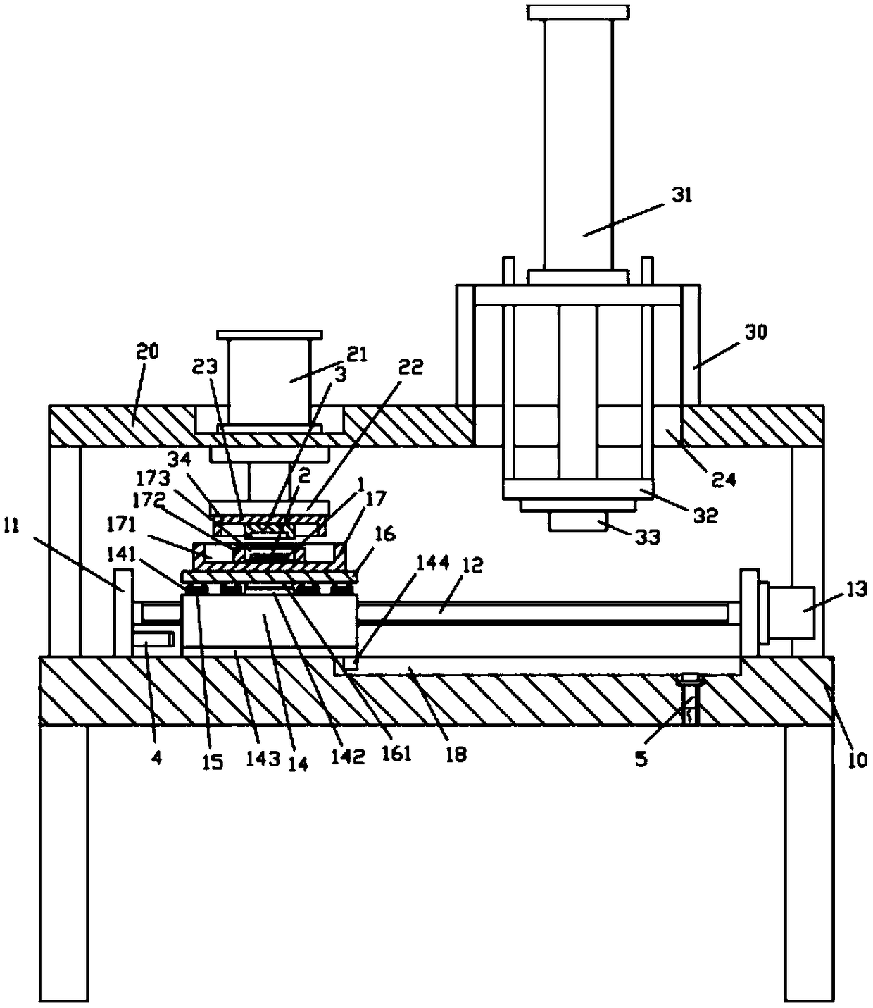
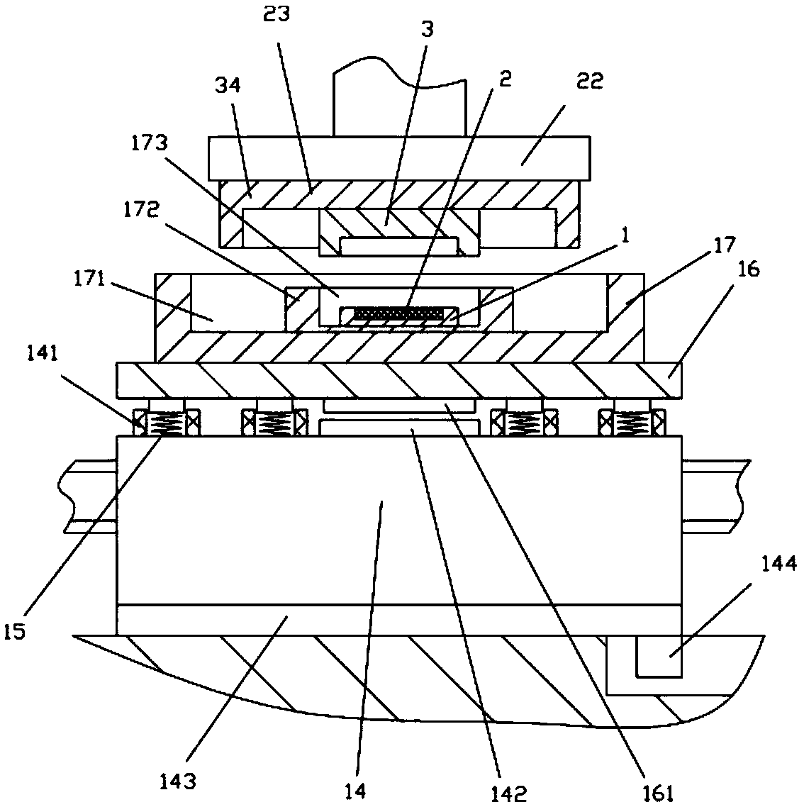
[0017] Examples, see e.g. Figure 1 to Figure 2 Shown, a kind of automobile small parts stamping grasping mechanism comprises frame 10, and the top of the top plate of described frame 10 is fixed with upper supporting frame 20, and the both sides of the top plate of frame 10 is fixed with vertical plate 11, and transmission The two ends of the screw rod 12 are hinged on two vertical plates 11, and a driving motor 13 is fixed on the outer wall of one of the vertical plates 11. The output shaft of the driving motor 13 is a spline shaft, and the spline shaft is sleeved on the transmission screw. In the spline hole provided at one end of 12, the moving block 14 is screwed in the drive screw 12, and the edge of the top surface of the moving block 14 is fixed with a plurality of buffer springs 15, and the upper end of the buffer spring 15 is fixed on the upper stamping support plate 16 On, the top surface of upper stamping support plate 16 is fixed with bottom stamping support block...


PUM


Abstract

The invention discloses a stamping and grasping mechanism for small automobile parts. The stamping and grasping mechanism comprises a rack. An upper supporting frame is fixed to the upper portion of a top plate of the rack, vertical plates are fixed to the two sides of the top plate of the rack, the two ends of a transmission screw are hinged to the two vertical plates, a driving motor is fixed to the outer side wall of one vertical plate, an output shaft of the driving motor is a spline shaft, the spline shaft is inserted into a spline hole formed in one end of the transmission screw in a sleeved manner, and a movable block is in screw joint with the interior of the transmission screw. Multiple buffer springs are fixed to the side portion of the top face of the movable block, the upper ends of the buffer springs are fixed to an upper stamping supporting plate, a bottom stamping supporting block is fixed to the top face of the upper stamping supporting plate, an installing groove is formed in the middle of the top face of the bottom stamping supporting block, an installing block is fixed to the middle of the bottom face of the installing groove, and an installing trough is formed in the middle of the top face of the installing block. The stamping and grasping mechanism is simple in structure, small in size, suitable for small-batch products, good in safety and good in effect, and meanwhile automatic unloading can be achieved without manual unloading.

Description

Technical field: [0001] The invention relates to the technical field of auto parts processing, and more specifically relates to a stamping and grabbing mechanism for small auto parts. Background technique: [0002] Existing mass production of auto parts is usually equipment with large volume and large structure, which needs a large output before it can be used. When only small batches of auto parts are produced, it is generally not necessary to use such processing equipment for processing , its energy consumption is too large, so it is necessary to use equipment with small volume and small structure, but there is no such structure at present. Generally, the products that need to be protruded are stamped by ordinary stamping equipment, and then unloaded manually, which is very Troublesome and not safe. Invention content: [0003] The purpose of the present invention is to overcome the deficiencies of the prior art and provide a stamping and grabbing mechanism for small aut...

Claims


Application Information

Patent Timeline
Patent Type & Authority Patents(China)
IPC IPC(8): B21D45/08
CPCB21D45/08
Inventor 李胜利
Owner 嵊州市高新技术发展有限公司
Learn More