Single-shaft shredder

A shredder and single-shaft technology, applied in the direction of grain processing, etc., can solve the problems of low crushing efficiency, low blanking efficiency, and non-contact of moving knives, and achieve the effect of improving crushing efficiency and reducing gaps

Inactive Publication Date: 2017-06-13
GENOX RECYCLING TECH
View PDF9 Cites 2 Cited by
  • Summary
  • Abstract
  • Description
  • Claims
  • Application Information

AI Technical Summary

Problems solved by technology

However, in the working process of existing shredders, when there are many or heavy materials, generally a large thrust is required to send the materials into the crushing cavity, and during the material pushing process, the thrust mechanism and the rotating There is often a large gap between the moving knives, not only the blanking efficiency is low, but also the moving knives cannot fully and fully contact with the material, resulting in low crushing efficiency

Method used


Image

  • Single-shaft shredder
  • Single-shaft shredder
  • Single-shaft shredder

Examples


Embodiment Construction

[0028] Below, in conjunction with accompanying drawing and specific embodiment, the present invention is described further:

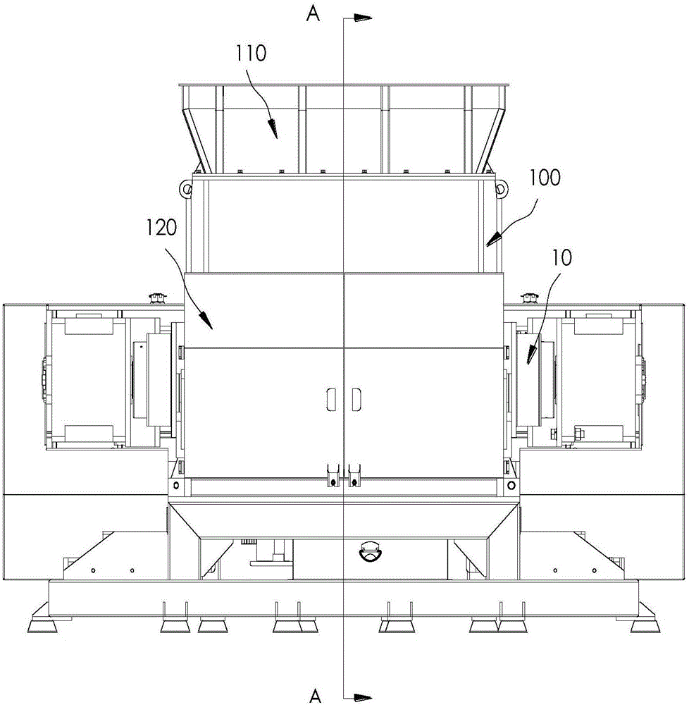
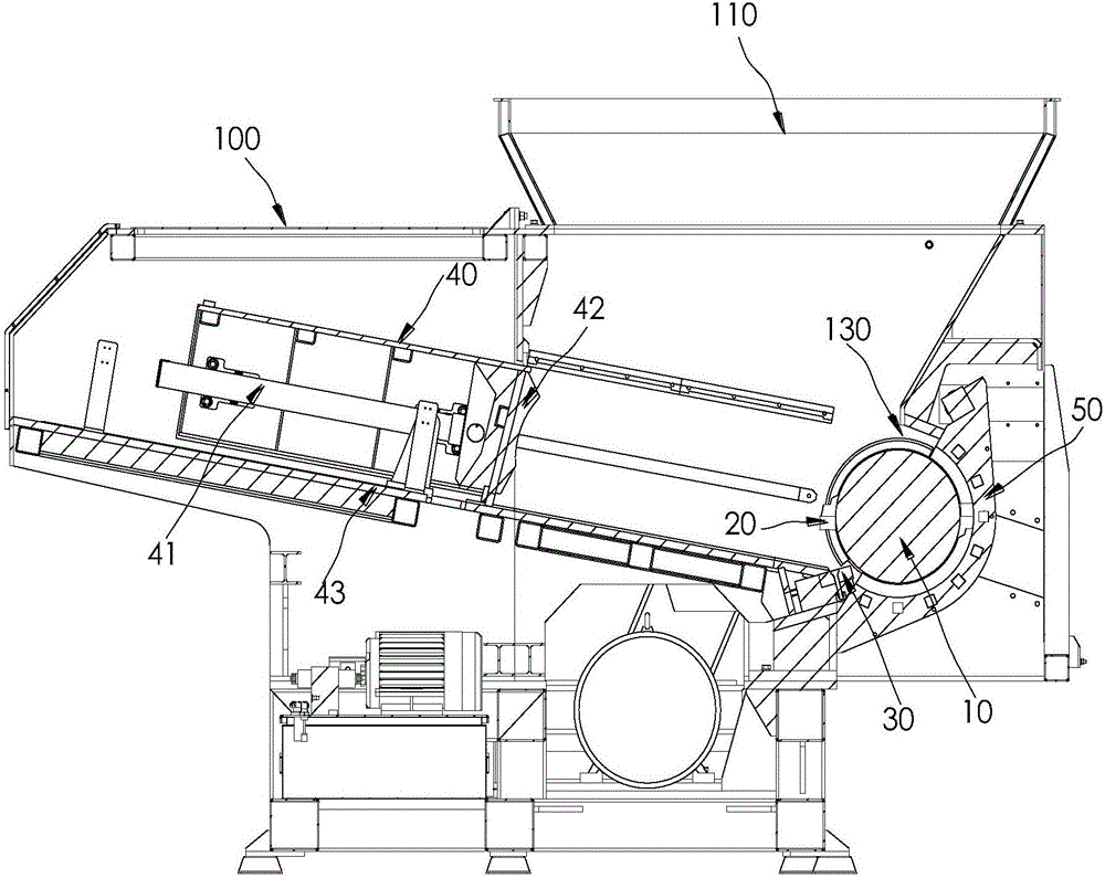
[0029] like figure 1 , figure 2 as well as image 3 The shown single-shaft shredder includes a box body 100 , a cutter assembly and a pushing mechanism, and a crushing cavity 130 is formed at one end of the box body 100 . The knife assembly specifically includes a fixed knife 30, a plurality of moving knives 20 and a knife shaft 10, so that the knife shaft 10 is pivotally connected in the crushing cavity 130, and a plurality of moving knives 20 are all installed on the outer surface of the knife shaft 10, and at the same time, the fixed knife The knife 30 is fixed on one side of the crushing chamber 130, so that the fixed knife 30 is spaced apart from the outer surface of the knife shaft 10 to form a cutting gap.

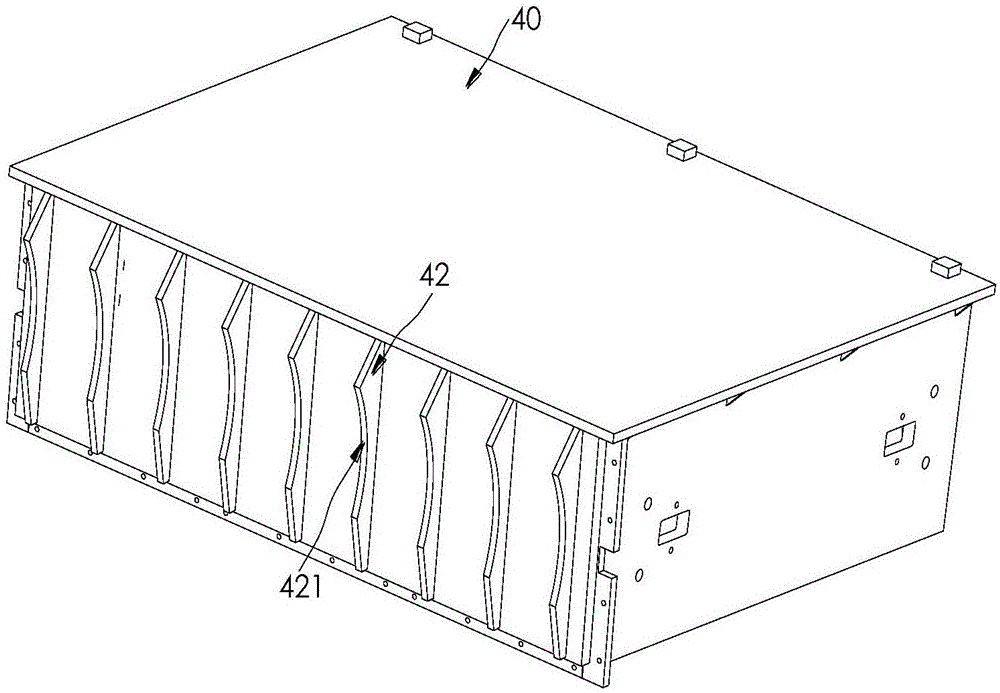
[0030] In addition, the above-mentioned pushing mechanism is installed at the end of the box body 100 away from the crushing chamber 130...


PUM


Abstract

The invention discloses a single-shaft shredder which comprises a box body, a tool assembly and a material pushing mechanism. A crushing cavity is formed in one end of the box body. The tool assembly comprises a fixed tool, a plurality of movable tools and a tool shaft, and the tool shaft is pivoted to the interior of the crushing cavity. The multiple movable tools are installed on the outer surface of the tool shaft. The fixed tool is fixedly arranged on one side of the crushing cavity. The fixed tool and the outer surface of the tool shaft are arranged in a spaced mode, and a cutting gap is formed. The material pushing mechanism comprises a material pushing box and a first driving device, and the first driving device is used for driving the material pushing box to move towards the crushing cavity. The end, close to the crushing cavity, of the material pushing box is fixedly provided with a plurality of material pushing strips, and the end faces, close to the crushing cavity, of the material pushing strips are provided with arc-shaped grooves matched with the outer circumference of the tool shaft. By the adoption of the single-shaft shredder, the blanking efficiency is improved, and the crushing efficiency of materials is improved.

Description

technical field [0001] The invention relates to the technical field of material recovery, in particular to a single-shaft shredder. Background technique [0002] Single-shaft shredder refers to a shredder with a single knife roller. There are multiple moving knives fixed on the knife shaft, and fixed knives are fixed in the corresponding box. When the driving mechanism drives the knife roller to rotate, the movement of the knife shaft The knife rotates around the central axis of the knife shaft. During the rotation of the moving knife, the blade of the moving knife will cut the material together with the blade of the fixed knife and tear the material into pieces. When crushing, the single-shaft shredder pours the material to be crushed into the box from the feed port on the box, and pushes the material into the crushing cavity under the action of the pushing plate in the box, so that the material Shearing, extrusion and tearing are carried out in the crushing chamber, so th...

Claims


Application Information

Patent Timeline
Patent Type & Authority Applications(China)
IPC IPC(8): B02C18/14B02C18/18B02C18/22B02C18/24B02C23/16
CPCB02C18/14B02C18/18B02C18/2233B02C18/24B02C23/16B02C2023/165B02C2201/06
Inventor 蒋经发陈新准
Owner GENOX RECYCLING TECH
Why Eureka
Try Eureka