
Magnetic-levitation wireless charger

A wireless charger and magnetic levitation technology, applied in current collectors, electric vehicles, electrical components, etc., can solve the problems of not meeting people's multi-directional choices, not reflecting fashion and individuality, not providing watch charging, etc., to meet the needs of the public, The effect of saving cost and prolonging the service life

Inactive Publication Date: 2017-06-09
GUANGDONG TANJIN ELECTRONICS TECH CO LTD
View PDF0 Cites 0 Cited by
  • Summary
  • Abstract
  • Description
  • Claims
  • Application Information

AI Technical Summary

Problems solved by technology

Based on the current magnetic levitation chargers and magnetic levitation lights are independent of each other, the magnetic levitation charger can only charge, the magnetic levitation light can only be used for lighting, and does not provide charging for watches; there are some restrictions on use, which cannot meet people's needs. Multi-directional choice, relatively monotonous in structural design, can not reflect fashion and personality

Method used


Image

  • Magnetic-levitation wireless charger
  • Magnetic-levitation wireless charger
  • Magnetic-levitation wireless charger

Examples


Embodiment

[0021] In order to enable the review committee to have a further understanding of the purpose, features and functions of the present invention, the preferred embodiments and the accompanying drawings are described in detail as follows:

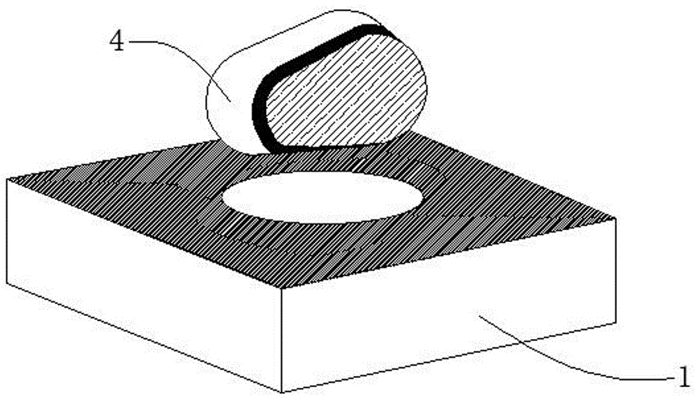
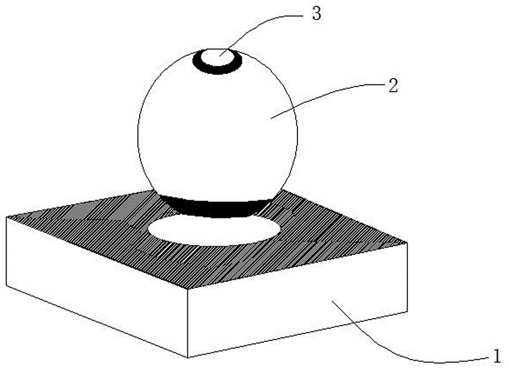
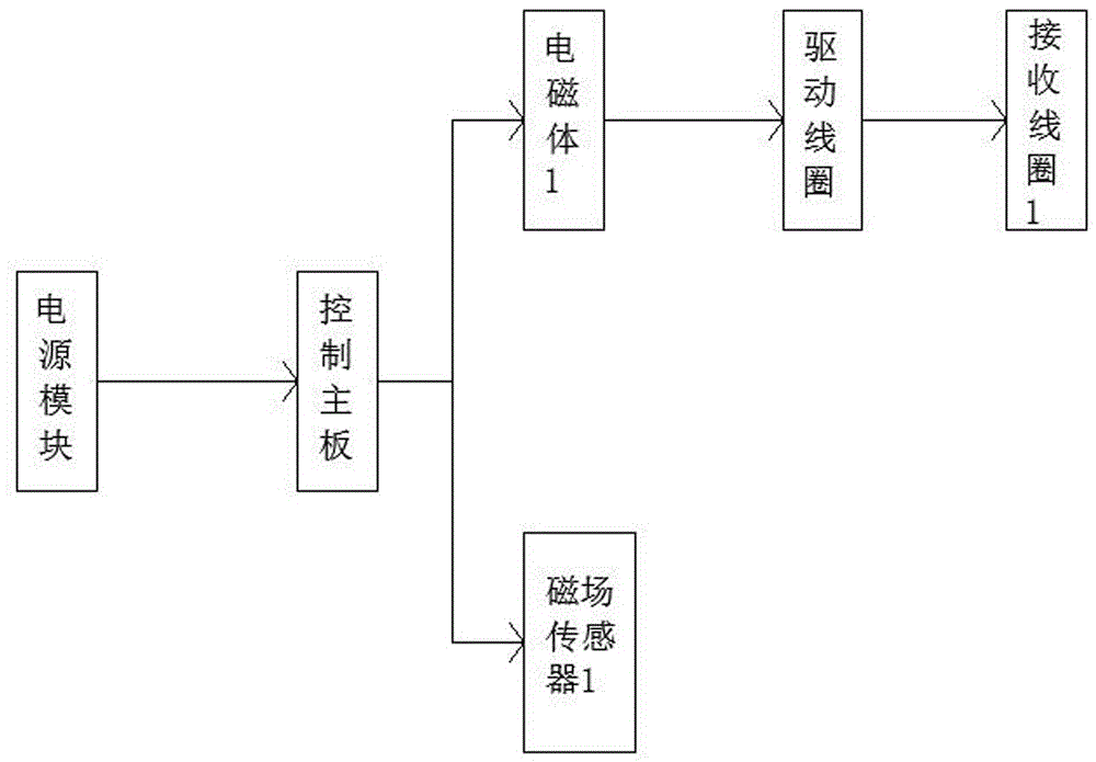
[0022] Please refer to the above drawings, which are structural schematic diagrams of preferred embodiments of the present invention. The present invention is a magnetically levitated wireless charger, including a base 1, a charging case 4 suspended above the base 1, and a smart light 2. The described The base 1 has a built-in power module, a control board, an electromagnet 1, and a driving coil; the charging cover 4 has a built-in magnetic field sensor 1, a receiving coil 1, and an electromagnet 2; the smart lamp 2 has a built-in light-emitting module, a magnetic field sensor 2, and a receiving The second coil and the third electromagnet; the control board includes a power-off protection device and a position sensor.

[0023] More specificall...

specific Embodiment approach

[0030] Specific implementation method: connect the power supply, when charging the mobile phone, you only need to place the mobile phone on the base 1 induction area; when charging the watch, put the watch on the charging cover 4, and then magnetically levitate on the base 1 When using the lighting, first remove the charging cover 4, then place the smart light 2 on the base 1 in the magnetic levitation state above the sensing area, and then lightly touch the touch start switch 3 to turn on the light. The invention has multi-directional use functions, cost saving, beautiful design, simple operation, satisfies the needs of the public, has great market prospects, and is worthy of popularization.


PUM


Abstract

The invention provides a magnetic levitation wireless charger, which relates to the field of magnetic levitation equipment, and mainly includes a base, a charging sleeve suspended above the base, and an intelligent light. The base has a built-in power module, a control board, an electromagnet, a driving coil, and a base A power interface is provided at any part of the side; the charging sleeve has a built-in magnetic field sensor, a receiving coil and an electromagnet 2. The control board includes a power-off protection device and a position sensor. The first electromagnet of the base and the two polarities of the electromagnet of the charging sleeve repel each other to suspend the charging sleeve in the air. The driving coil transmits the electricity generated by the electromagnet to the receiving coil , and then processed by the magnetic field sensor, so as to charge the device to be charged. As long as you put the watch on the charging case, you can charge it wirelessly; you don’t need to use the charging case to charge the mobile phone, you can directly place the mobile phone on the base for charging; there is a switch on the top of the smart light, place the smart light on the base and lightly touch the start switch to start lighting .

Description

technical field [0001] The invention relates to the field of magnetic levitation equipment, in particular to a magnetic levitation wireless charger. Background technique [0002] With the rapid development of social science and technology, maglev is an emerging technology in recent years. It is used in various industries, such as transportation, electronic technology and household appliances. Among them, maglev wireless charging uses the principle of maglev, and various maglev chargers or maglev lights appear on the market. . Based on the current magnetic levitation chargers and magnetic levitation lights are independent of each other, the magnetic levitation charger can only charge, the magnetic levitation light can only be used for lighting, and does not provide charging for watches; there are some restrictions on use, which cannot meet people's needs. Multi-directional selection, relatively monotonous in structural design, can not reflect fashion and individuality. Con...

Claims


Application Information

Patent Timeline
IPC IPC(8): H02J7/00H02J50/10
CPCH02J7/025
Inventor 郭增州
Owner GUANGDONG TANJIN ELECTRONICS TECH CO LTD
Learn More