
Heat storage chamber

A technology of regenerator and regenerator, applied in the field of regenerator, can solve the problems of poor heat storage effect, uneven air distribution, complicated structure of grate bars, etc. simple effect

Pending Publication Date: 2017-06-06
SHENWU TECH GRP CO LTD
View PDF0 Cites 2 Cited by
  • Summary
  • Abstract
  • Description
  • Claims
  • Application Information

AI Technical Summary

Problems solved by technology

[0002] The grate brick structure in the related art adopts the grate brick structure to bear the weight of the upper checker brick. The grate structure is complicated. Gas and air enter the regenerator from the lower part of the regenerator through the grate. Poor thermal effect

Method used


Image

  • Heat storage chamber
  • Heat storage chamber
  • Heat storage chamber

Examples


Embodiment Construction

[0031] Embodiments of the invention are described in detail below, examples of which are illustrated in the accompanying drawings. The embodiments described below by referring to the figures are exemplary and are intended to explain the present invention and should not be construed as limiting the present invention.

[0032] In describing the present invention, it should be understood that the terms "center", "longitudinal", "transverse", "length", "width", "thickness", "upper", "lower", "front", " Back", "Left", "Right", "Vertical", "Horizontal", "Top", "Bottom", "Inner", "Outer", "Axial", "Radial", "Circumferential", etc. The indicated orientation or positional relationship is based on the orientation or positional relationship shown in the drawings, and is only for the convenience of describing the present invention and simplifying the description, rather than indicating or implying that the referred device or element must have a specific orientation, or in a specific orien...


PUM


Abstract

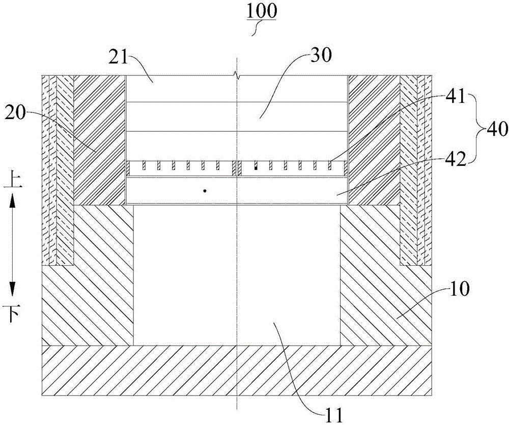
The invention discloses a heat storage chamber. The heat storage chamber comprises a lower enclosing wall, an upper enclosing wall, a heat storage body and an airflow distributor, wherein a flue with an opening top is defined by the inner peripheral wall of the lower enclosing wall; the upper enclosing wall is arranged on the top of the lower enclosing wall, and a mounting cavity communicating with the flue is defined by the inner peripheral wall of the upper enclosing wall; the heat storage body is mounted inside the mounting cavity; and the airflow distributor is arranged inside the mounting cavity, located at the bottom of the heat storage boxy and provided with a plurality of overflowing through holes, and each overflowing through hole makes the flue and the heat storage body communicate. According to the heat storage chamber in the embodiment, a fire bar arch brick structure in correlation techniques is replaced with the airflow distributor provided with the multiple overflowing through holes, so that cost is reduced; and through the airflow distributor, uniform airflow can be obtained, a bias current phenomenon is prevented, local thermal stress is eliminated, and the performance of the heat storage chamber is improved.

Description

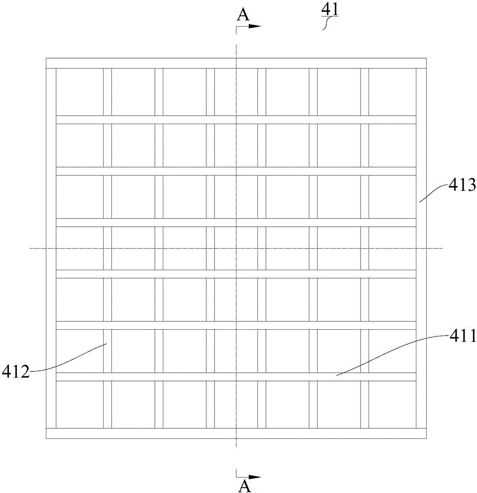
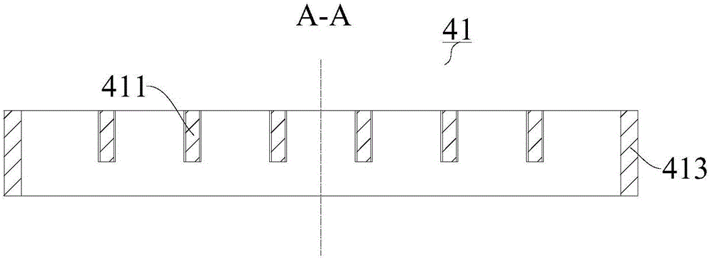
technical field [0001] The present invention relates to the technical field of heat storage equipment, and more specifically, to a heat storage chamber. Background technique [0002] The grate brick structure in the related art adopts the grate brick structure to bear the weight of the upper checker brick. The grate structure is complicated. Gas and air enter the regenerator from the lower part of the regenerator through the grate. The thermal effect is poor. Contents of the invention [0003] The present invention aims to solve one of the technical problems in the related art at least to a certain extent. [0004] For this reason, the present invention proposes a regenerator with a simple structure and uniform airflow distribution. [0005] The regenerator according to the embodiment of the first aspect of the present invention comprises: a lower enclosure wall, the inner peripheral wall of which defines a flue with an open top; an upper enclosure wall, which is arrange...

Claims


Application Information

Patent Timeline
Patent Type & Authority Applications(China)
IPC IPC(8): F27D17/00F23D14/66
CPCF23D14/66F27D17/004F27D2017/007Y02E20/34
Inventor 裴芬刘行波谢善清吴道洪
Owner SHENWU TECH GRP CO LTD
Learn More