An outdoor storage fan

An outdoor and fan technology, applied in the field of electric fans, can solve the problems of inability to use manually, the battery power is exhausted, and the air volume is small, so as to reduce the reverse electromagnetic force, facilitate positioning, and reduce the rotating force.

Active Publication Date: 2019-12-17
NINGBO JIANGBEI YIHE IND DESIGN
View PDF8 Cites 0 Cited by
  • Summary
  • Abstract
  • Description
  • Claims
  • Application Information

AI Technical Summary

Problems solved by technology

[0002] Existing electric fans are essential electrical appliances in summer, especially for outdoor sports enthusiasts. Flying insects and heat in the wild are unbearable when camping in summer, and existing electric fans are either particularly large in size or have a particularly small air volume. Either it is difficult to carry or the wind volume is very small
At the same time, the outdoor environment is complex, and ordinary electric fans are difficult to adapt to different environments.
Because the fan is used outdoors, the user cannot carry a battery with a large amount of power, and the electric fan is likely to run out of battery power when used outdoors, and the existing electric fan cannot manually rotate the blades after the power is used up, so Cannot be used manually after a power outage

Method used


Image

  • An outdoor storage fan
  • An outdoor storage fan
  • An outdoor storage fan

Examples


Embodiment Construction

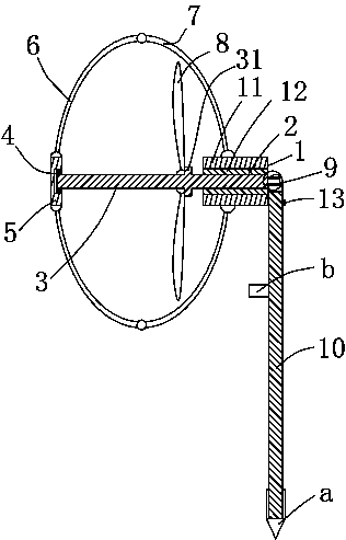
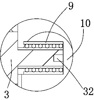
[0012] The present invention will be described in further detail below in conjunction with accompanying drawing and specific embodiment: see Figure 1 to Figure 4 , an outdoor storage fan, including a motor 1, the motor 1 includes a stator 11 on the outer ring and a rotor 12 on the inner ring, the stator 11 and the rotor 12 can be slidably separated, and the rotor 12 is A polygonal through hole 2 is provided, and a polygonal rotating shaft 3 matching it is provided on the polygonal through hole 2. One end of the polygonal rotating shaft 3 is connected with a front end face 5 through a first bearing 4, and the front end face 5 is circumferentially aligned with several One end of the front frame 6 is rotatably connected, the outer side of the stator 11 is rotatably connected with one end of the plurality of rear frames 7, and the other ends of the plurality of front frames 6 are rotatably connected with the other ends of the plurality of rear frames 7 one by one. 5 and the polyg...


PUM


Abstract

The invention discloses an outdoor foldable fan. The outdoor foldable fan comprises a stator and a rotor of a motor, wherein the stator and the rotor can slide relative to each other. The rotor is provided with a polygonal through hole. A polygonal rotating shaft is arranged on the polygonal through hole. One end of the polygonal rotating shaft is connected with a front end face through a first bearing. The circumferential direction of the front end face is rotationally connected with one end of a plurality of front frameworks. The outer side of the stator is rotationally connected with one end of each of a plurality of back frameworks. The other end of each back framework is correspondingly and rotationally connected with the other end of the corresponding back framework. The portion, between the front end face and the motor, of the polygonal rotating shaft is rotationally provided with fan blades. The polygonal rotating shaft is provided with a protruding ring used for locating the fan blades. The other end of the polygonal rotating shaft is connected with a supporting rod through a second bearing. The supporting rod is identical with the polygonal rotating shaft in peripheral structure. The outer ring of the second bearing is rotationally connected with the supporting rod. The side face of the stator is provided with a clamping portion. The end of the supporting rod is provided with a drill bit. The outdoor foldable fan can be folded and is large in blowing capacity, convenient to carry and convenient to place and locate in various outdoor environments.

Description

technical field [0001] The invention belongs to the technical field of electric fans, in particular to an outdoor storage fan. Background technique [0002] Existing electric fans are essential electrical appliances in summer, especially for outdoor sports enthusiasts. Flying insects and heat in the wild are unbearable when camping in summer, and existing electric fans are either particularly large in size or have a particularly small air volume. Either it is difficult to carry or the wind volume is very small. At the same time, the outdoor environment is complicated, and it is difficult for ordinary electric fans to adapt to different environments. Because the fan is used outdoors, the user cannot carry a battery with a large amount of power, and the electric fan is likely to run out of battery power when used outdoors, and the existing electric fan cannot manually rotate the blades after the power is used up, so Cannot be used manually after power failure. Contents of ...

Claims


Application Information

Patent Timeline
Patent Type & Authority Patents(China)
IPC IPC(8): F04D25/08F04D29/00F04D29/38H02K7/14
CPCF04D25/08F04D29/002F04D29/388H02K7/14
Inventor 蒋维娜
Owner NINGBO JIANGBEI YIHE IND DESIGN
Why Eureka
Try Eureka