Tool with automatic drilling pressure adjustment function

An automatic adjustment and tool technology, which is applied in the direction of drill pipe, drill pipe, drilling equipment, etc., can solve the problems of difficult to achieve high-efficiency drilling, the effect of improving the drilling speed is not obvious, and the wear of the drill bit is intensified, so as to reduce the collapse of the drill bit The probability of avoiding serious economic losses and the effect of reducing drill bit wear

Active Publication Date: 2017-05-31
SOUTHWEST PETROLEUM UNIV
View PDF6 Cites 3 Cited by
  • Summary
  • Abstract
  • Description
  • Claims
  • Application Information

AI Technical Summary

Problems solved by technology

[0002] In recent years, with the increasing difficulty of oil extraction, horizontal wells, highly deviated wells, small-diameter wells, deep wells, and sidetracked wells from old wells account for an increasing proportion of drilling. In this case, it is difficult to achieve high efficient drilling
During the drilling process, due to the friction between the drill string and the well wall and the drill bit encountering rock formations with different hardness, the real-time WOB required by the drill bit fluctuates to a certain extent, but the drilling pressure applied on the ground is applied to the drill bit after a long transmission. , it is easy to cause too much or too little pressure applied to the drill bit
If the drilling pressure is too low, the drilling speed will be very slow; if the drilling pressure is too high, the wear of the drill bit will be intensified, and the improvement effect of the drilling speed will not be obvious, and even the drilling effect will be deteriorated

Method used


Image

  • Tool with automatic drilling pressure adjustment function

Examples


Embodiment Construction

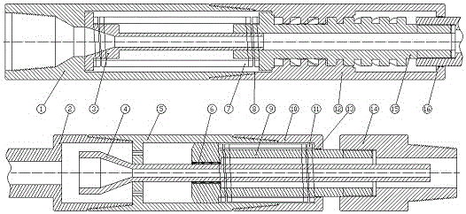
[0008] As shown in the drawings, this tool is composed of connecting parts (upper joint 1, connecting tube 2, lower joint 14), energy storage part (spring inner sleeve 3, multi-strand coil spring 7), helical spline part (inner Helical spline cylinder 12, external helical spline shaft 15), pressurized part (Y-shaped runner sleeve 4, pressurized slide tube 5, pressurized piston shaft 9, combined sealing tube 10, multi-strand coil spring 11) 1. Other components (sealing ring 6, gasket 8, sealing collar 16 and pipe threads everywhere) are composed of five parts. The tool is connected with other drilling tools through the external thread of the lower joint 14 at the lower end of the mandrel and the internal thread of the upper joint 1 . Due to the throttling effect of the Y-shaped flow channel sleeve type 4, a high-pressure zone is formed in the lower cylinder sleeve of the tool, and the lower cavity of the pressurized piston shaft 9 forms a low-pressure zone due to the annular spa...


PUM


Abstract

The invention discloses a tool with an automatic drilling pressure adjustment function. The tool is connected with other well drilling tools through an outer thread of a lower connector of the lower end of a mandrel and an inner thread of an upper connector. A plurality of spiral springs in the upper connector store energy and are fixed into the upper connector, and the upper connector is connected with an inner spiral spline cylinder in a threaded mode. Inner and outer spiral splines are of rectangular tooth profiles. An outer spiral spline shaft is connected with the upper side of a connection sleeve through a thread, and a pressurizing slide pipe is connected with the lower side of the connection sleeve though a pipe thread. A runner sleeve pipe with a Y-shaped lower portion is in interference fit with the pressurizing slide pipe through a bearing. A pressurizing piston shaft is connected to a drill bit. A key groove in the pressurizing slide pipe can allow the pressurizing piston shaft to slide up and down therein. A separation layer is arranged in the middle, and four round holes are distributed evenly in the separation plate. The tool has the advantages that abrasion of the drill bit during well drilling is relieved effectively through automatic pressure adjustment; during deep well drilling and horizontal well drilling, stable drilling pressure of the drill bit can be kept, rock breaking can be effectively assisted, sticking of the tool and back-pressure can be reduced, utilization rate of the drill bit can be increased, and cost can be reduced.

Description

technical field [0001] The invention relates to an automatic adjustment drill pressure tool used in oil and gas drilling engineering, tunnel engineering, geological drilling, especially oil and gas field drilling. Background technique [0002] In recent years, with the increasing difficulty of oil extraction, horizontal wells, highly deviated wells, small-diameter wells, deep wells, and sidetracked wells from old wells account for an increasing proportion of drilling. In this case, it is difficult to achieve high efficient drilling. During the drilling process, due to the friction between the drill string and the well wall and the drill bit encountering rock formations with different hardness, the real-time WOB required by the drill bit fluctuates to a certain extent, but the drilling pressure applied on the ground is applied to the drill bit after a long transmission. , It is easy to cause too much or too little pressure applied to the drill bit. If the drilling pressure ...

Claims


Application Information

Patent Timeline
Patent Type & Authority Applications(China)
IPC IPC(8): E21B19/086
CPCE21B19/086
Inventor 郭亮邱竞雄明新程
Owner SOUTHWEST PETROLEUM UNIV
Why Eureka
Try Eureka