
Stand column welding tool

A welding tool and column technology, applied in welding equipment, auxiliary welding equipment, welding/cutting auxiliary equipment, etc., can solve the problems of low efficiency, excessive flange assembly gap, low production efficiency, etc., to improve work efficiency, Guaranteed installation accuracy

Inactive Publication Date: 2017-05-31
湖南中佳华悦环保科技有限公司
View PDF12 Cites 2 Cited by
  • Summary
  • Abstract
  • Description
  • Claims
  • Application Information

AI Technical Summary

Problems solved by technology

[0002] At present, the four columns of the vertical garbage compressor are welded by the column guide rail and the flange plate by scribing and laying simple ribs. This method has low production efficiency and requires a high technical level of the producer. It is difficult to guarantee the design requirements of the drawings, and the following problems are prone to occur:
[0003] 1. The flange plate is not perpendicular to the guide rail of the column, and the guide wheel jams when it moves up and down;
[0004] 2. The assembly gap of the flange plate is too large, and the stability of the equipment is poor during operation;
[0005] 3. The columns cannot be used in common with each other, and must be welded during assembly, which is inefficient;
[0006] 4. On-site installation can only be assembled, which increases the difficulty of installation;
[0007] 5. The distance between the column guide rails cannot be guaranteed, and it takes time to adjust the clearance of the guide wheels

Method used


Image

  • Stand column welding tool
  • Stand column welding tool
  • Stand column welding tool

Examples


Embodiment Construction

[0034] In order to make the technical problems solved by the present invention, the technical solutions adopted and the technical effects achieved clearer, the present invention will be further described in detail below in conjunction with the accompanying drawings and embodiments. It should be understood that the specific embodiments described here are only used to explain the present invention, but not to limit the present invention.

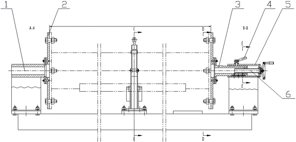
[0035] refer to Figure 1-2 , the invention discloses a column welding tool, comprising: a stand 13, a fixed seat 1, a movable seat, a support seat 12, and a pressing mechanism;

[0036] A fixed seat 1 is installed at one end of the stand 13, and a movable seat is installed at the other end;

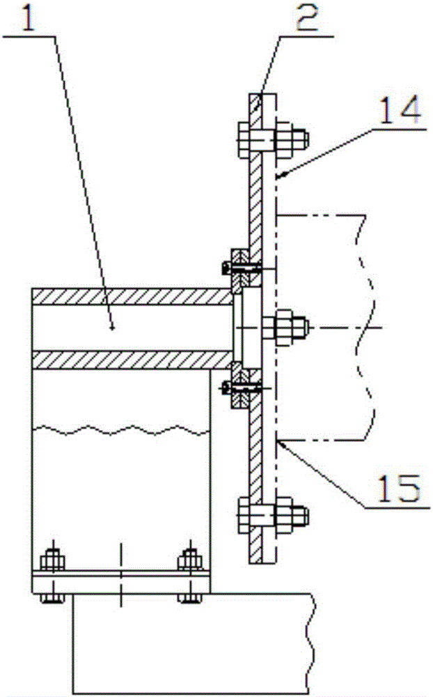
[0037] refer to Figure 3-4 , the fixed seat 1 includes: a fixed sleeve and a seat body installed up and down, and a positioning disc 2 is vertically installed on the mounting surface of the fixed sleeve;

[0038] refer to Figure 5-6 , the movable s...


PUM


Abstract

The invention discloses a stand column welding tool which comprises a rack, a fixed seat, a movable seat and a supporting seat. The fixed seat is installed at one end of the rack, and the movable seat is arranged at the other end of the rack. The fixed seat comprises a fixed sleeve and a seat body which are arranged in an up-and-down manner, wherein the installation face of the fixed sleeve is perpendicularly provided with a positioning disc. The movable seat comprises a guide seat, a seat body, a movable sleeve, a screw rod and a hand wheel, wherein the guide seat and the seat body are installed in an up-and-down manner, the hand wheel rotates to drive the screw rod to rotate, and the screw rod rotates to drive the movable sleeve to move front and back. The supporting seat is installed at the position, between the fixed seat and the movable seat, of the rack. According to the V-shaped structure formed by the supporting seat, stand column guide rails can automatically centered and do not need to be straightened; flange plates are positioned through reamed holes, and the requirement for the form and location tolerance between the flange plates and stand columns can be met; the requirement for the length size is met through moving of the movable sleeve; deformation generated during welding can be controlled through a pressing mechanism, and therefore the requirement for the parallelism, perpendicularity and the location degree between the stand column guide rails and the flange plates and between the flange plates are met.

Description

technical field [0001] The invention relates to the field of environmental protection equipment manufacturing, in particular to a column welding tool, which is especially suitable for welding the column of a vertical garbage compressor. Background technique [0002] At present, the four columns of the vertical garbage compressor are welded by the column guide rail and the flange plate by scribing and laying simple ribs. This method has low production efficiency and requires a high technical level of the producer. It is difficult to guarantee the design requirements of the drawings, and the following problems are prone to occur: [0003] 1. The flange plate is not perpendicular to the guide rail of the column, and the guide wheel jams when it moves up and down; [0004] 2. The assembly gap of the flange plate is too large, and the stability of the equipment is poor during operation; [0005] 3. The columns cannot be used in common with each other, and must be welded during ...

Claims


Application Information

Patent Timeline
Patent Type & Authority Applications(China)
IPC IPC(8): B23K37/04
CPCB23K37/0443
Inventor 罗杰华刘保国彭其灿
Owner 湖南中佳华悦环保科技有限公司
Learn More