A tripper chipping riveting jig and riveting method thereof
A technology for riveting fixtures and trippers, applied in electrical components, emergency protection devices, circuits, etc., can solve problems such as difficulty in controlling force, affecting product quality, product knocking deformation, etc., to improve product quality stability and extrusion effect. Better, better squeeze tightness
- Summary
- Abstract
- Description
- Claims
- Application Information
AI Technical Summary
Problems solved by technology
Method used
Image
Examples
Embodiment 1
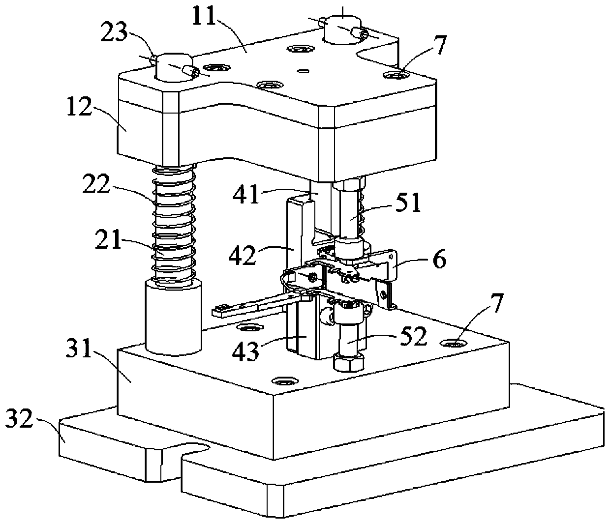
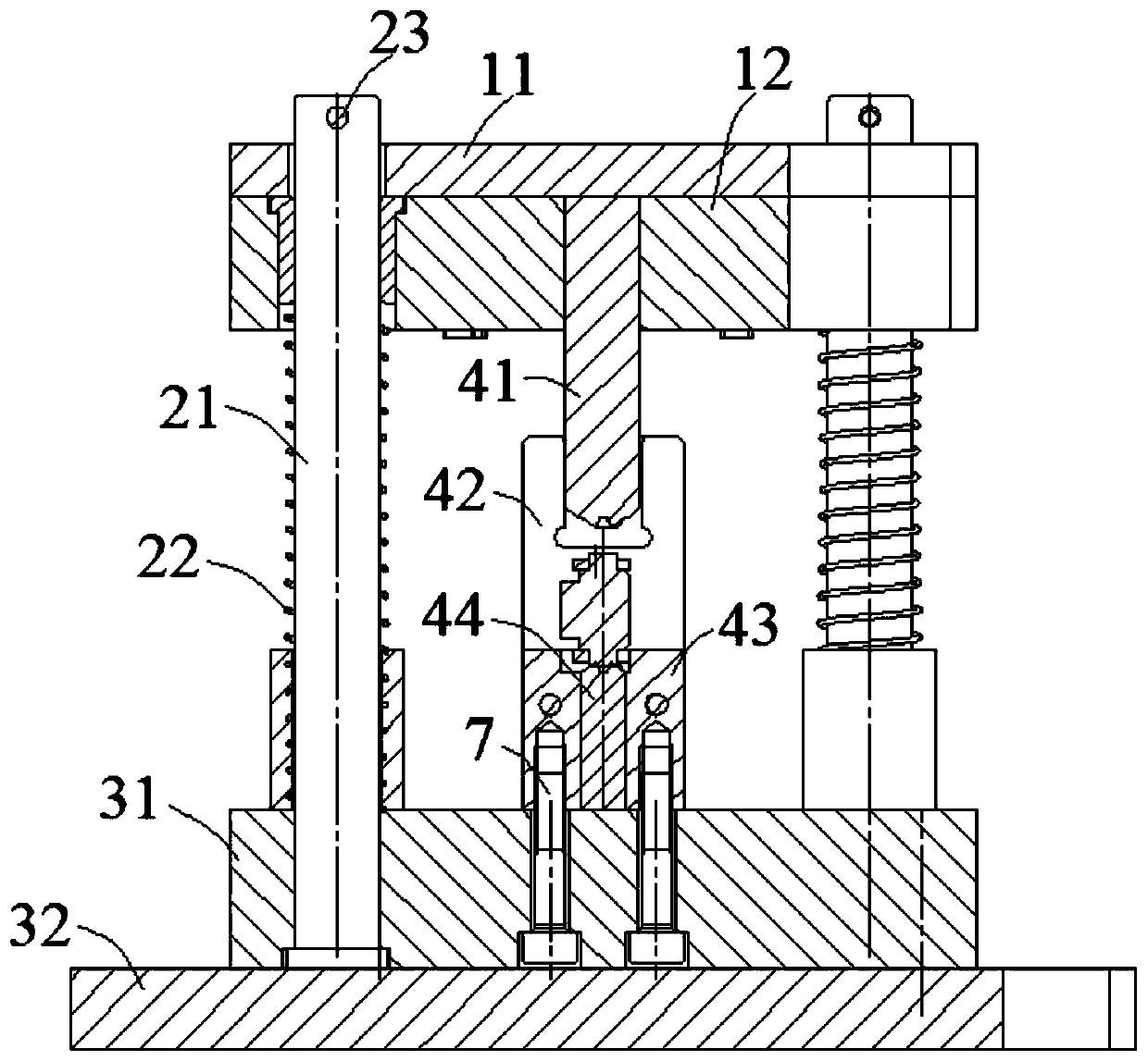
[0050] to combine figure 1 and figure 2 , a tripper chisel riveting jig of this embodiment mainly meets the performance requirements of the new generation product KFM2 for the riveting and assembly of tripper components. Its core design principle is: the riveting fixture tooling adopts an integrated assembly structure, and the upper mold slides up and down under the guidance of two guide columns. For the convenience of the staff, a U-shaped positioning block is designed in the middle of the fixture. When the staff When the pre-assembled release is put into the fixture, the riveting point of the release can be conveniently and quickly placed under the upper and lower punches without mold matching. The structure of the riveting fixture will be introduced in detail below:
[0051] The riveting fixture of this embodiment includes an upper die, a guide post 21 , a return spring 22 , a lower die, an upper punch 41 , a rear baffle 42 , a U-shaped positioning block 43 and a lower ...
Embodiment 2
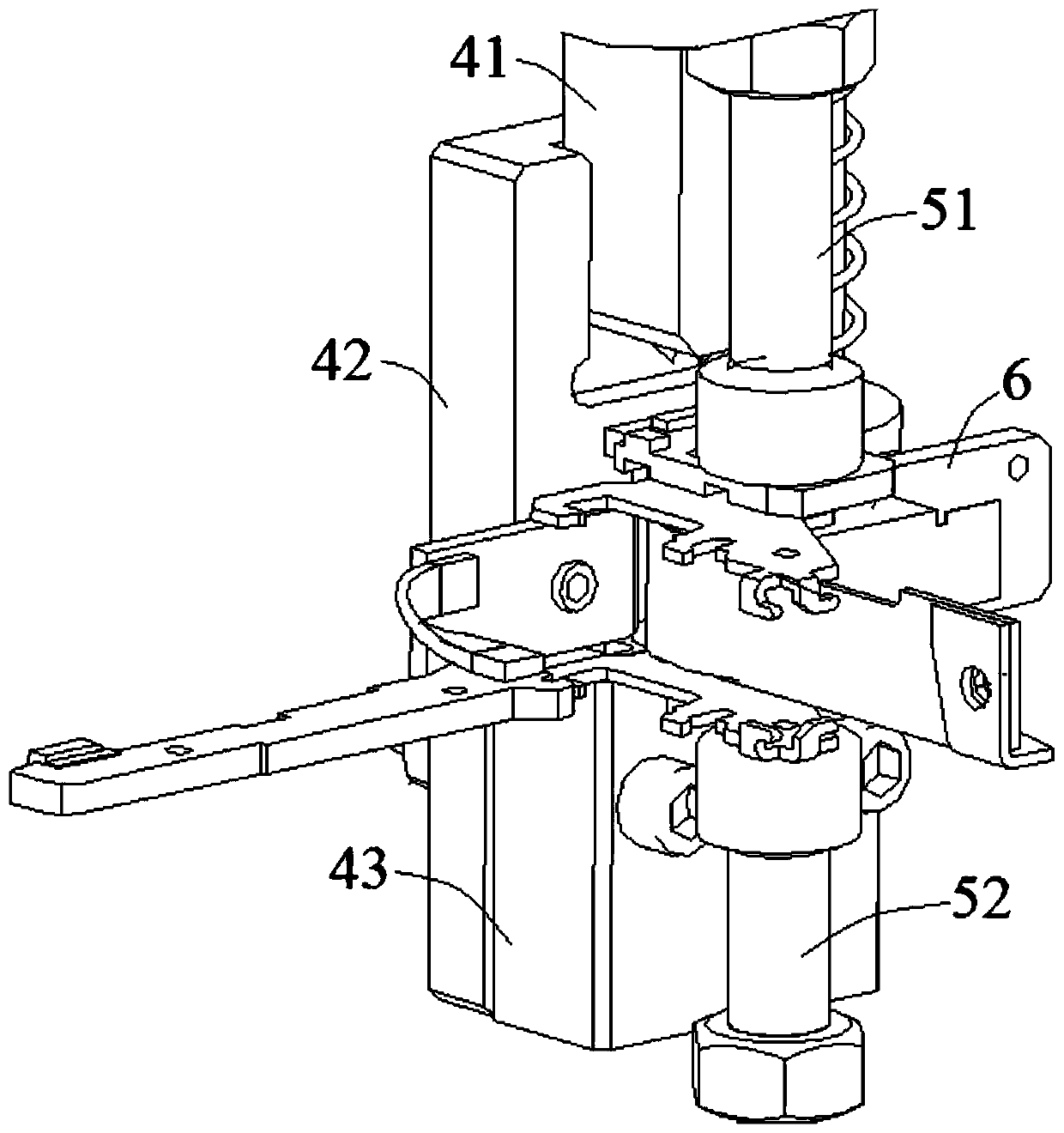
[0058] A chisel-opening riveting jig for a tripper in this embodiment is basically the same as in Embodiment 1, except that the chisel-opening riveting jig of this embodiment also includes an upper shaping column 51 and a lower shaping column 52, the upper One end of the shaping column 51 is provided with a briquetting block, and the other end is provided with a threaded section. The upper shaping column 51 is connected to the upper mold through the set threaded section. One end of the lower shaping column 52 is also provided with a briquetting block, and the other end is provided with a There is a threaded section, and the lower shaping column 52 is also connected with the lower mold through the provided threaded section.
[0059] In this embodiment, the upper shaping column 51 and the lower shaping column 52 are arranged. On the one hand, the lower shaping column 52 can cooperate with the U-shaped positioning block 43, and the initially assembled release can be stably placed ...
Embodiment 3
[0066] A chisel-open riveting jig for a tripper in this embodiment is basically the same as in Embodiment 2, except that the structural dimensions of the upper punch blade 411 and the lower punch blade 441 in this embodiment are both triangular teeth The tooth depth L1 is 2.5mm, the distance L2 between the teeth is 3mm, the angle α between the dedendums of two teeth is 30°, and the angle β between the teeth is 95°.
PUM
| Property | Measurement | Unit |
|---|---|---|
| length | aaaaa | aaaaa |
Abstract
Description
Claims
Application Information
 - Generate Ideas
- Intellectual Property
- Life Sciences
- Materials
- Tech Scout
- Unparalleled Data Quality
- Higher Quality Content
- 60% Fewer Hallucinations
Browse by: Latest US Patents, China's latest patents, Technical Efficacy Thesaurus, Application Domain, Technology Topic, Popular Technical Reports.
© 2025 PatSnap. All rights reserved.Legal|Privacy policy|Modern Slavery Act Transparency Statement|Sitemap|About US| Contact US: help@patsnap.com


