
Driving circuit for display panel and display device

A driving circuit and display panel technology, applied to static indicators, instruments, etc., can solve problems such as uneven boundary lines, uneven gray scales, and brightness differences, and achieve the effect of improving display quality and solving uneven gray scales

Active Publication Date: 2017-05-24
KUSN INFOVISION OPTOELECTRONICS
View PDF5 Cites 12 Cited by
  • Summary
  • Abstract
  • Description
  • Claims
  • Application Information

AI Technical Summary

Problems solved by technology

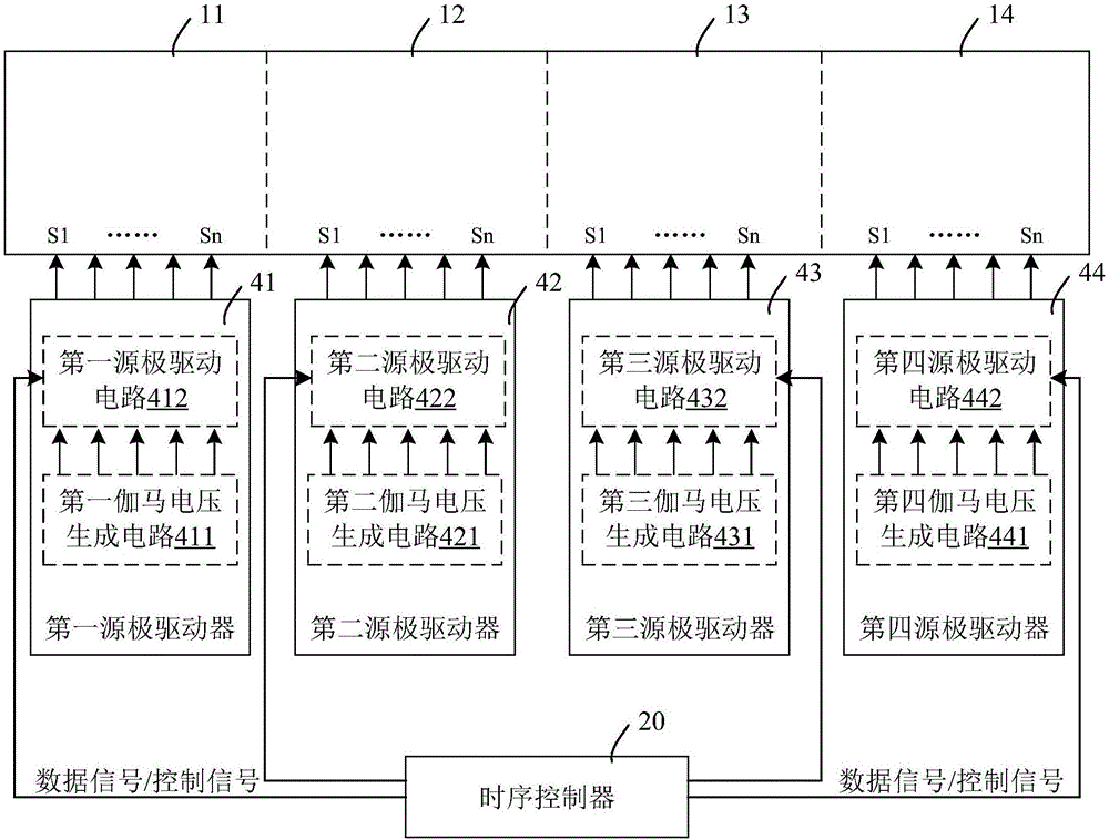
[0007] Since the gamma voltage generation circuits of each source driver 41 to 44 are independent, the inconsistency between the different gamma voltages generated can lead to differences in the luminance of the four partitions at the same gray scale, resulting in gray scale Uneven (and possibly uneven dividing lines)

Method used


Image

  • Driving circuit for display panel and display device
  • Driving circuit for display panel and display device
  • Driving circuit for display panel and display device

Examples


Embodiment Construction

[0027] Various embodiments of the invention will be described in more detail below with reference to the accompanying drawings. In the various drawings, the same elements are denoted by the same or similar reference numerals. For the sake of clarity, various parts in the drawings have not been drawn to scale.

[0028] The invention can be embodied in various forms, some examples of which are described below.

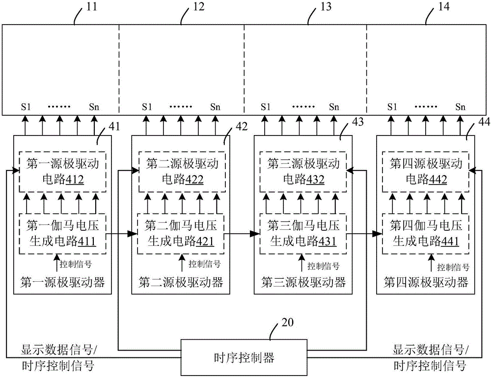
[0029] image 3 A schematic block diagram of a driving circuit for a display panel in a liquid crystal display device according to an embodiment of the present invention is shown. like image 3 As shown, in the case of a large-sized display panel, the display area may be divided into a plurality of display areas.

[0030] Correspondingly, the drive circuit includes: a timing controller 20 for providing different timing control signals and display data signals to multiple display areas; multiple source drivers 41-44, each of which corresponds to the A corresponding d...


PUM


Abstract

The invention discloses a driving circuit for a display panel. The display panel comprises a plurality of display areas. The driving circuit comprises a time sequence controller, a plurality of source drives and a plurality of gamma voltage generation circuits, wherein the time sequence controller is used for providing different time sequence control signals and display data signals to a plurality of display areas; each source drive corresponds to one corresponding display area in the plurality of the display areas, and is used for providing gray scale voltage corresponding to the display data signals to corresponding display areas on the basis of the time sequence control signals; the plurality of the gamma voltage generation circuits are respectively arranged on corresponding source drives of the plurality of the source drive and form a cascading circuit, and are used for providing a plurality types of gamma voltage to corresponding source drive in a cascading mode; and the plurality types of the gamma voltage are used for generating reference voltage of the gray scale voltage for corresponding source drives. By adopting the driving circuit, problems such as gray scale unbalance caused by a plurality of driving circuits in a large-size display panel can be relieved, alleviated or eliminated.

Description

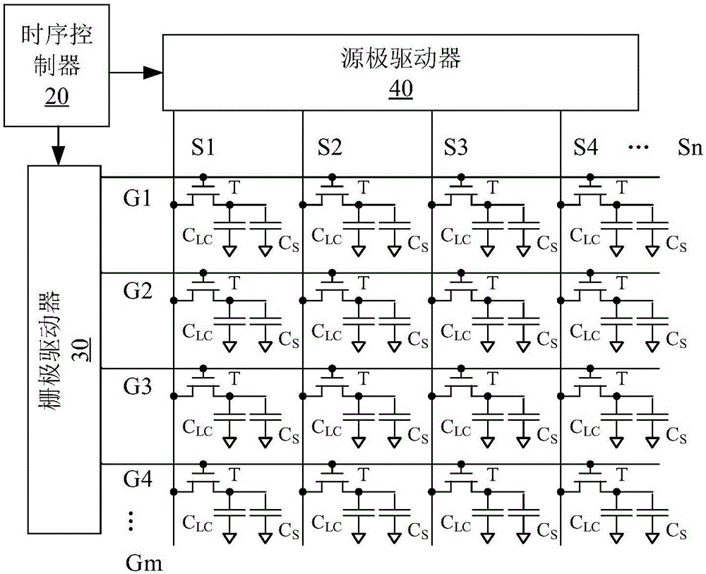
technical field [0001] The invention belongs to the technical field of displays, and more specifically relates to a driving circuit and a display device for a display panel. Background technique [0002] Due to the advantages of thinness, energy saving, and low power consumption, liquid crystal display devices have been widely used in electronic equipment such as televisions, computers, mobile phones, and digital cameras. [0003] figure 1 An equivalent circuit diagram of a liquid crystal display device according to the prior art is shown. The display panel 10 of the liquid crystal display device includes a first glass substrate and a second glass substrate, the first surface of the first glass substrate is opposite to the first surface of the second glass substrate. A plurality of gate scanning lines and a plurality of source data lines intersecting each other are formed on the first surface of the first glass substrate, and a selection thin film transistor and a pixel el...

Claims


Application Information

Patent Timeline
Patent Type & Authority Applications(China)
IPC IPC(8): G09G3/36
Inventor 张晓娥穆兰
Owner KUSN INFOVISION OPTOELECTRONICS
Learn More