LED display screen correction method

A technology of LED display and calibration method, applied in static indicators, instruments, etc., can solve the problems of inability to solve the problem of bright and dark lines, difficulty in ensuring the stability of the adjustment effect, and high dependence on operator experience, so as to eliminate the split screen splicing line. problems, eliminate the problem of splicing bright and dark lines, avoid manual adjustment of splicing lines or the effect of setting up the camera for local re-calibration work

Active Publication Date: 2017-05-24
XIAN NOVASTAR TECH
View PDF7 Cites 17 Cited by
  • Summary
  • Abstract
  • Description
  • Claims
  • Application Information

AI Technical Summary

Problems solved by technology

Related technical solution one can obtain the physical seam information between the split screen and the split screen, and solve the problem of bright and dark lines caused by the difference in the physical seam between the split screen and the split screen, but there are also the following disadvantages: 1) Calibration requires setting up a camera and analyzing parameters, which takes a long time; and 2) When configuring a new display, if the width of the LED pixel is not selected reasonably, it may bring new differences in brightness and chromaticity due to the trend of data distribution. Personnel requirements are higher
Related technical solution 2 largely solves the difference in brightness and chromaticity between split screens and split screens due to data distribution trends, but because it cannot obtain the physical seam information between split screens and split screens, it cannot solve the problem of split screens. The problem of bright and dark lines caused by the difference in physical seams between screens and split screens requires manual adjustment. Manual adjustment relies too much on the operator's experience, and it is difficult to ensure the stability of the adjustment effect. Moreover, the adjustment time is too long and the efficiency is too high. Low

Method used


Image

  • LED display screen correction method
  • LED display screen correction method
  • LED display screen correction method

Examples


Embodiment Construction

[0023] In order to make the above objects, features and advantages of the present invention more comprehensible, specific implementations of the present invention will be described in detail below in conjunction with the accompanying drawings.

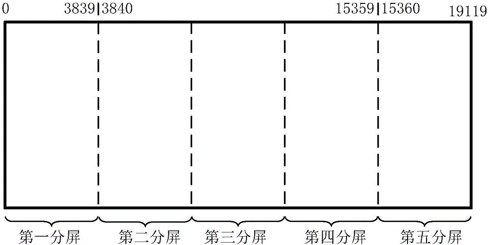
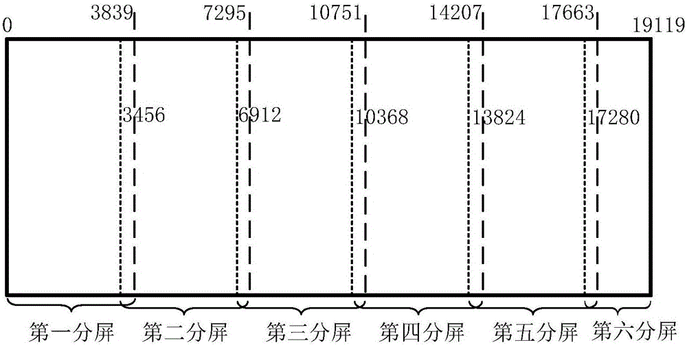
[0024] Specifically, the following embodiments of the present invention propose a new solution for correcting bright and dark lines between sub-screens of super-large LED display screens, including the step of splitting the screen and the step of compensating the difference in brightness and chromaticity between the sub-screens; Eliminate split-screen splicing line problems caused by inconsistent data distribution trends between split screens, effectively alleviate or even eliminate splicing light and dark line problems caused by physical splicing between split screens, and avoid manual adjustment of splicing by on-site calibration personnel line or set up the camera for partial recalibration.

[0025] In the following, the resolution ...


PUM


Abstract

The invention provides an LED display screen correction method, which comprises the steps of: dividing an LED display screen into a plurality of split screens, wherein every two adjacent split screens have an overlap region and comprises a first split screen and a second split screen; correcting each first split screen to obtain a first split screen correction coefficient file; and switching an input side connecting relation of receiving cards loaded with the overlap regions of the first split screens and the second split screens from a front-end LED display controller connected and loaded with the first split screens to a front-end LED display controller connected and loaded with the second split screens, and correcting each second split screen to obtain a second split screen correction coefficient file. Therefore, the LED display screen correction method can effectively alleviate and even eliminate the problem of split screen splicing lines caused by the inconsistency of data distribution among the split screens, effectively alleviates and even eliminates the problem of splicing bright and dark lines due to physical seam abutting among the split screens, and avoids the manual adjustment of the splicing lines by field correction personnel or the arrangement of a camera for conducting partial re-correction operation.

Description

technical field [0001] The invention relates to the technical field of LED correction, in particular to a method for correcting an LED display screen. Background technique [0002] With the development of the LED display industry, there are more and more small-pitch, high-resolution displays, people have higher and higher requirements for display quality, and the frequency of using correction systems is increasing. However, due to the limitation of DVI , when the LED display screen is larger than a certain resolution, the on-site control system or graphics card cannot be loaded point-to-point at one time, and cannot be calibrated at one time. Screen calibration, while split-screen calibration cannot know the brightness and chromaticity distribution of other screens that are naturally spliced ​​with it and the physical gap distance information, so that after the on-site calibration is completed, human eyes are prone to splicing line problems caused by bright color differences...

Claims


Application Information

Patent Timeline
Patent Type & Authority Applications(China)
IPC IPC(8): G09G3/32
CPCG09G3/32G09G2300/026
Inventor 郑瑞涛赵星梅
Owner XIAN NOVASTAR TECH
Why Eureka
Try Eureka