Driving device

A drive device and drive shaft technology, applied in elastic couplings, mechanical equipment, couplings, etc., can solve the problems of easy damage, unreasonable structural design of the drive shaft, not meeting the needs of production, etc., to avoid damage. , Reasonable structure design, prolong service life effect

Inactive Publication Date: 2017-05-24
姚素梅
View PDF0 Cites 0 Cited by
  • Summary
  • Abstract
  • Description
  • Claims
  • Application Information

AI Technical Summary

Problems solved by technology

The existing drive shaft structure design is unreasonable, does not meet the needs of production, and is easily damaged

Method used


Image

  • Driving device

Examples


Embodiment Construction

[0010] The present invention will be further explained below in conjunction with the accompanying drawings and embodiments.

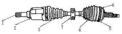
[0011] Such as figure 1 As shown, a driving device includes a drive shaft body 1, and the drive shaft body 1 is provided with an inner constant velocity joint housing 2, an inner coupling shaft 3, a pulse wheel 4 and an outer constant velocity joint housing 5 in sequence. , the inner constant velocity joint housing 2 or the outer constant velocity joint housing 5 is connected with a dust cover 6 . The inline shaft 3 is provided with a damping counterweight 7 .

[0012] The above content is an example and description of the present invention, but it does not mean that the advantages that the present invention can obtain are limited by this, any simple transformation of the structure that may be possible in the practice of the present invention, and / or one of the advantages realized in some embodiments or more are within the protection scope of the pres...


PUM


Abstract

The invention discloses a driving device. The driving device comprises a driving shaft body (1). The driving shaft body (1) is sequentially provided with an inner constant velocity universal joint casing (2), an inner coupling (3), a pulse wheel (4) and an outer constant velocity universal joint casing (5). The inner constant velocity universal joint casing (2) or the outer constant velocity universal joint casing (5) is connected with a dust cover (6). The driving device is reasonable in structural design, the production and life needs are met, damage is avoided, the service life is prolonged, and the requirement of industrial production can be met.

Description

technical field [0001] The invention relates to the mechanical field, in particular to a driving device. Background technique [0002] The drive shaft is the working device of the loader, which is a device that can advance the smoothness of the loader so that the drive wheels can rotate at different angular velocities. The structure design of the existing drive shaft is unreasonable, does not meet the needs of production, and is easily damaged. Contents of the invention [0003] The object of the present invention overcomes the problems of the prior art to provide a driving device. [0004] The driving device of the present invention includes a drive shaft body, on which an inner constant velocity universal joint housing, an inner coupling shaft, a pulse wheel and an outer constant velocity universal joint housing are sequentially arranged, and the inner constant velocity universal joint housing A dust cover is attached to the joint shell or the outer constant velocity j...

Claims


Application Information

Patent Timeline
Patent Type & Authority Applications(China)
IPC IPC(8): F16D3/16F16D3/84
Inventor 姚素梅何平
Owner 姚素梅
Why Eureka
Try Eureka