A pressure pulsation attenuation device with adjustable attenuation frequency integrated in the plunger pump

A technology for attenuating frequency and pressure pulsation, which is applied to components, pump elements, machines/engines, etc. of elastic fluid pumping devices, and can solve the problems of ineffective attenuation of pressure pulsation and hydraulic pump source pressure pulsation, etc., to improve Space utilization, adjustable attenuation frequency, and compact structure

Active Publication Date: 2018-05-08
ZHEJIANG UNIV
View PDF10 Cites 0 Cited by
  • Summary
  • Abstract
  • Description
  • Claims
  • Application Information

AI Technical Summary

Problems solved by technology

[0005] The purpose of the present invention is to solve the problem of the pressure pulsation of the hydraulic pump source and the problem that the traditional pulsation attenuator with fixed attenuation frequency cannot effectively attenuate the pressure pulsation with changing frequency, and specially provides an adjustable attenuation frequency integrated in the plunger pump The pressure pulsation attenuator can efficiently attenuate the pressure pulsation amplitude output by the plunger pump, and can adjust the attenuation frequency according to the piston pump speed to maximize the pulsation attenuation effect in a wide frequency band

Method used


Image

  • A pressure pulsation attenuation device with adjustable attenuation frequency integrated in the plunger pump
  • A pressure pulsation attenuation device with adjustable attenuation frequency integrated in the plunger pump
  • A pressure pulsation attenuation device with adjustable attenuation frequency integrated in the plunger pump

Examples


Embodiment Construction

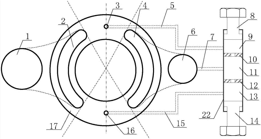
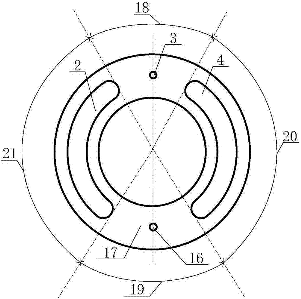
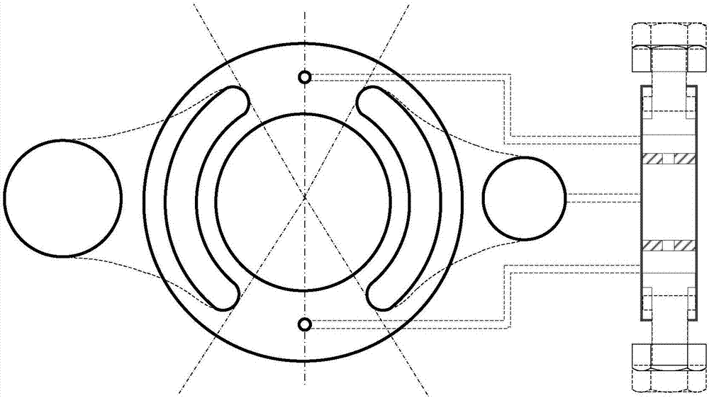
[0022] The present invention will be further described in detail below in conjunction with the drawings and embodiments:

[0023] The plunger pump includes an oil suction port 1, an oil suction groove 2, an oil discharge groove 4, and an oil discharge port 6. The oil suction groove 2 and the oil discharge groove 4 are arranged on the valve plate 17, and the present invention is arranged and connected to the valve plate 17 of the plunger pump. Such as figure 1 As shown, it specifically includes a top dead center pressure buffer mechanism, an oil drain buffer mechanism, and a bottom dead center pressure buffer mechanism. The top dead center pressure buffer mechanism includes a top dead center orifice 3, an upper thin tube 5, an upper buffer cavity 9, and an upper adjustment The nut 8 and the through hole of the upper hole damping sheet 10, the bottom dead center pressure buffer mechanism includes the bottom dead center damping hole 16, the lower thin tube 15, the lower buffer cavity...


PUM


Abstract

The invention discloses a pressure pulsation attenuation device integrated in a plunger pump and capable of adjusting the attenuation frequency. A sleeve is arranged outside the plunger pump. An upper damping fin with a hole and a lower damping fin with a hole are fixed in the sleeve. A cavity in the sleeve is divided by the upper damping fin with the hole and the lower damping fin with the hole into an oil drainage buffer cavity, an upper buffer cavity and a lower buffer cavity. A sleeve port at the position of the upper buffer cavity is connected with an upper adjusting nut. A sleeve port at the position of the lower buffer cavity is connected with a lower adjusting nut. The portions, between the two ends of an oil suction groove and an oil drainage groove, of a thrust plate are provided with an upper dead center damping hole and a lower dead center damping hole correspondingly, the upper dead center damping hole and the lower dead center damping hole communicate with the upper buffer cavity and the lower buffer cavity through an upper thin pipe and a lower thin pipe correspondingly, and an oil outlet is connected with the oil drainage buffer cavity through an oil drainage thin pipe. The inherent flow refill amplitude of the plunger pump can be effectively attenuated, the pulsation amplitude of pump high-pressure oil drainage pressure is effectively attenuated, and the attenuation frequency is adjustable. The pressure pulsation attenuation device can be integrated in a shell of the plunger pump and is applicable to various hydraulic plunger pumps.

Description

Technical field [0001] The invention relates to a pressure pulsation attenuator, in particular to a pressure pulsation attenuation device with adjustable attenuation frequency integrated in a plunger pump, and belongs to the technical field of fluid transmission and control. Background technique [0002] Fluid mechanical systems generally have flow pulsation and pressure pulsation, such as the flow pulsation of pipeline caused by the pump source of the hydraulic system, and the water hammer phenomenon of valve opening and closing. These flow and pressure pulsations will not only affect the normal operation of the system, but also reduce the performance of the system. If the pulsation induces large pipeline vibration, it will reduce the life of pipelines and hydraulic components, and in severe cases may even cause rupture of the pipe wall, damage to the pipeline support structure, and decrease in support rigidity, causing failure of the pipeline system and loss of hydraulic oil. ...

Claims


Application Information

Patent Timeline
Patent Type & Authority Patents(China)
IPC IPC(8): F04B53/00F04B53/04
CPCF04B53/00F04B53/04
Inventor 欧阳小平张鹤然方旭王天照杨华勇
Owner ZHEJIANG UNIV
Why Eureka
Try Eureka