
Oven hinge with two-way buffering function

A two-way buffering and functional technology, applied in the field of oven hinges, can solve problems such as high production costs, vibration, and cumbersome installation, and achieve the effects of improving market competitiveness, improving operating quality, and running quietly and smoothly

Pending Publication Date: 2017-05-24
FOSHAN SHUNDE NUOWEI ELECTRIC CO LTD
View PDF11 Cites 0 Cited by
  • Summary
  • Abstract
  • Description
  • Claims
  • Application Information

AI Technical Summary

Problems solved by technology

In actual use, due to the certain acceleration of the spring reset, when the furnace door is about to close, it has the largest kinetic potential energy, the speed is also faster, and the sound of closing the door is relatively loud, and the box is easily damaged if it is subjected to such impact for a long time , the general method is to add shock absorbers on the door frame, such as sponges, etc., but the tension spring of this method still has a lot of potential energy and is still easy to damage
Another method is to set guide rails, springs and rollers inside the hinge to cooperate with each other to achieve deceleration and pause, but its complex structure and relatively cumbersome installation lead to relatively high production costs
In addition, the existing oven hinges can only provide one-way buffering when the door is closed, but there is no buffering when the oven door is opened, vibrations will still occur, and the impact of the limiting parts will cause noise and other disadvantages. Therefore, it is necessary to modify the existing oven door. Hinge for further improvement

Method used


Image

  • Oven hinge with two-way buffering function
  • Oven hinge with two-way buffering function
  • Oven hinge with two-way buffering function

Examples


Embodiment Construction

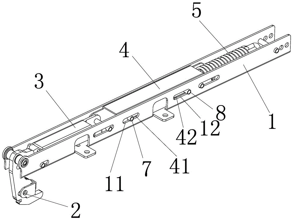
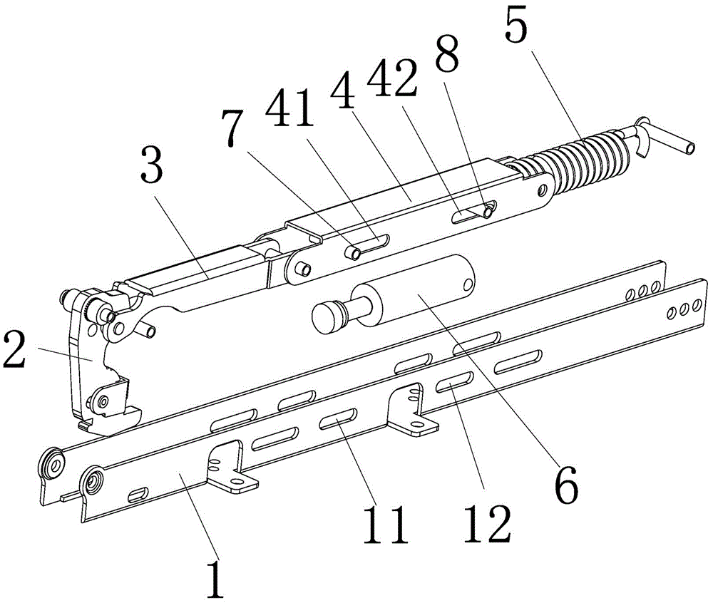
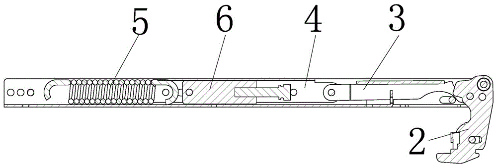
[0021] The present invention will be specifically and further described below in conjunction with the accompanying drawings. An oven hinge with two-way buffering function, which includes a main casing 1 and a hinge arm 2 arranged at its end, the hinge arm 2 is hingedly mounted on the main casing 1 in a swingable manner, and inside the main casing 1 The first pull arm 3 is also installed, the front end of the first pull arm 3 is hinged with the hinge arm 2, the rear end of the first pull arm 3 is hinged with the second pull arm 4, and the tail end of the second pull arm 4 is connected with the main housing 1. A tension spring 5 is provided, and the tension spring 5 generates tension to drive the hinge arm 2 to rotate inwards through the first and second tension arms 3 and 4 to generate the power to close the door. It is characterized in that: the main housing 1 is also provided with a buffer 6, the front end of the buffer 6 is equipped with a first connecting rod 7, the first c...


PUM


Abstract

Provided is an oven hinge with a two-way buffering function. The oven hinge with the two-way buffering function comprises a main shell and a hinge arm arranged at the end of the main shell. The hinge arm is hinged to the main shell in a swinging mode. A first pull arm is further installed in the main shell. A tension spring is arranged between the tail end of the second pull arm and the main shell. The tension spring generates tension force and drives the hinge arm to rotate inwards through the first pull arm and the second pull arm, so that power for closing a door is generated. The oven hinge with the two-way buffering function is characterized in that a buffer is further arranged in the main shell; a first connection rod is installed at the front end of the buffer and inserted in a first guide hole in the second pull arm and a second guide hole in the main shell in a penetrating mode; and a second connection rod is installed at the rear end of the buffer and inserted in a third guide hole in the second pull arm and a fourth guide hole in the main shell in a penetrating mode. The oven hinge with the two-way buffering function has the beneficial effects that the unique buffer drive structure can achieve two-way buffering when the hinge is opened or closed, operation quality is improved, and the oven hinge can operate quietly and stably.

Description

technical field [0001] The invention relates to an oven hinge, in particular to an oven hinge with two-way buffering function. Background technique [0002] The door hinge of the existing cabinet basically relies on the tension or elastic force of the spring, and adopts the method of twisting and pulling. When the door needs to be opened, the furnace door is pulled open to lengthen or compress the spring, which can realize the opening of the furnace door. When it needs to be closed When the furnace door is closed, just let go, and the furnace door will be closed due to the reset action of the spring. In actual use, due to the certain acceleration of the spring reset, when the furnace door is about to close, it has the largest kinetic potential energy, the speed is also faster, and the sound of closing the door is relatively loud, and the box is easily damaged if it is subjected to such impact for a long time , the general method is to add shock absorbers on the door frame, ...

Claims


Application Information

Patent Timeline
Patent Type & Authority Applications(China)
IPC IPC(8): E05F5/08E05D3/06
CPCE05D3/06E05F5/08E05Y2900/308
Inventor 胡国衡
Owner FOSHAN SHUNDE NUOWEI ELECTRIC CO LTD
Learn More