
Automatic assembly equipment for small slider components

A technology of automatic assembly and small slider, applied in assembly machines, metal processing equipment, manufacturing tools, etc., can solve the problems of high labor intensity of employees, high labor costs, and low operating efficiency, and achieve the effect of saving labor costs.

Active Publication Date: 2018-11-23
GREE ELECTRIC APPLIANCES ZHENGZHOU
View PDF7 Cites 0 Cited by
  • Summary
  • Abstract
  • Description
  • Claims
  • Application Information

AI Technical Summary

Problems solved by technology

[0002] In the air-conditioning industry, the air outlet of the cabinet-type air conditioner is usually designed with a small sliding door panel. This structure requires a pair of slider assemblies during assembly, such as figure 1 As mentioned above, the small slider assembly 10 is assembled from three parts: the rubber block 12, the slider 14 and the screw 16. At present, the small slider assembly 10 still relies on manual assembly, and the existing mode has the following disadvantages: 1. Operational efficiency Low, the output per hour is only about 200 pieces
2. The labor cost is high, and this position still requires 1 person to operate
3. The labor intensity of the employees is high, and about 2,000 pieces need to be pre-installed every day

Method used


Image

  • Automatic assembly equipment for small slider components
  • Automatic assembly equipment for small slider components
  • Automatic assembly equipment for small slider components

Examples


Embodiment Construction

[0036] Hereinafter, the present invention will be described in detail with reference to the drawings and the embodiments. It should be noted that the following embodiments and the features in the embodiments can be combined with each other if there is no conflict.

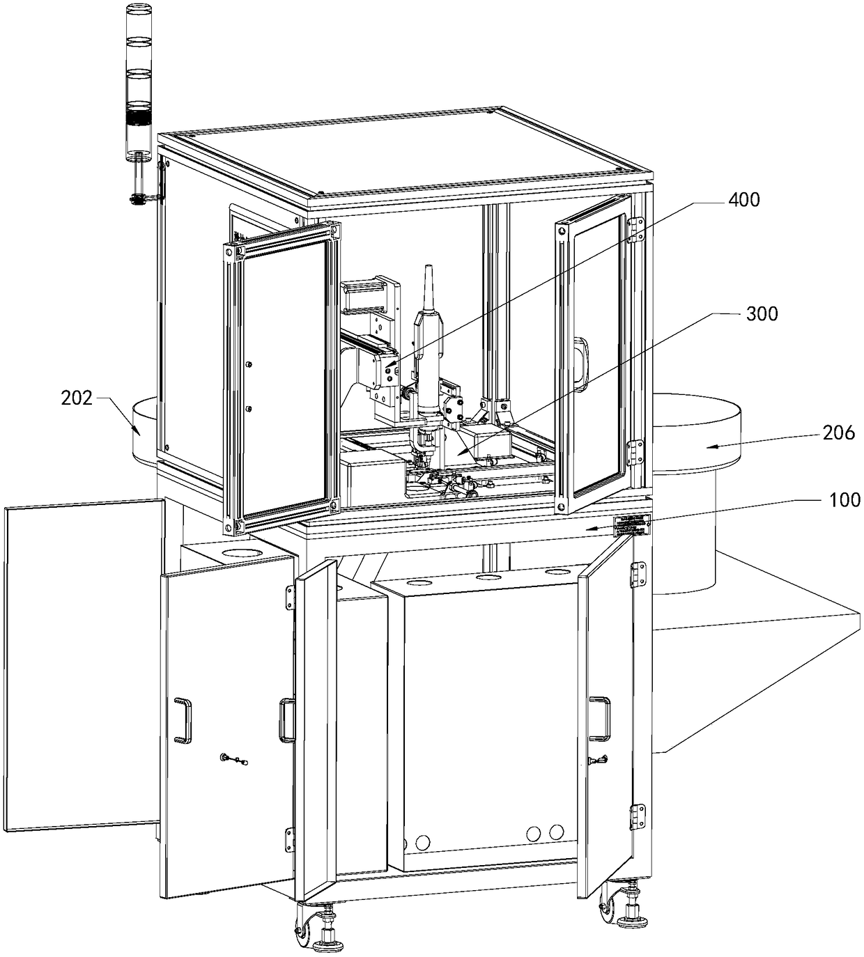
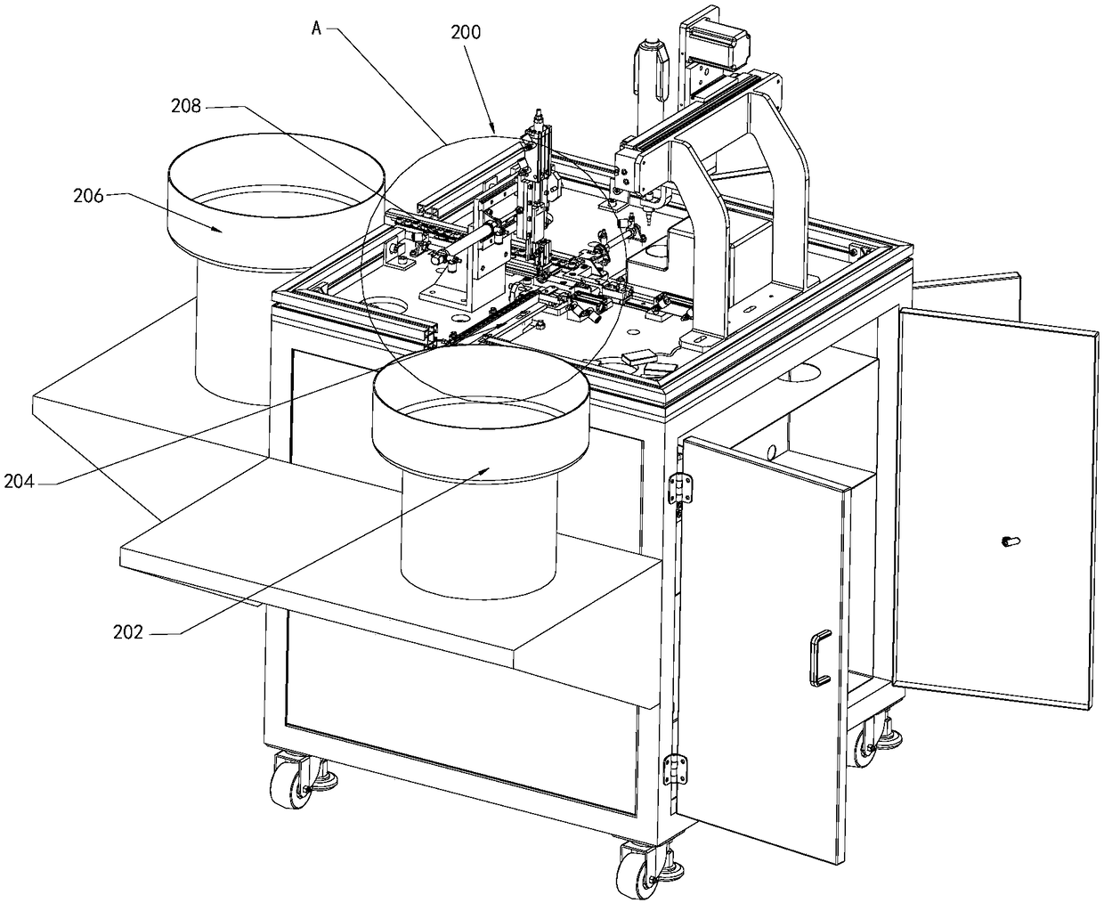
[0037] figure 2 This is a three-dimensional schematic diagram of the small slider assembly automatic assembly equipment in one of the embodiments of the present invention. As shown in the figure, the small slider assembly automatic assembly equipment mainly consists of a frame 100, a feeding system 200, and a rubber block slider assembly mechanism 300. It consists of a small slider assembly conveying mechanism, an automatic screwing mechanism 400 and a finished product blanking mechanism 500.

[0038] The feeding system 200 is arranged on the frame 100 and is used to transport the rubber block 12 and the sliding block 14 to the grasping position and the assembly position, respectively. Such as image 3 , 4 As shown, t...


PUM


Abstract

The invention discloses an automatic assembling device for a small sliding block assembly. The automatic assembling device for the small sliding block assembly comprises a machine frame, a feeding system, a rubber block and sliding block assembling mechanism, a small sliding block assembly conveying mechanism, an automatic screw installing mechanism and a finished product discharging mechanism, wherein the feeding system is arranged on the machine frame and used for conveying a rubber block and a sliding block to a grabbing position and an assembling position correspondingly, the rubber block and sliding block assembling mechanism is arranged on the machine frame and used for assembling the rubber block at the grabbing position and the sliding block at the assembling position together, the small sliding block assembly conveying mechanism is used for conveying the rubber block and the sliding block which are assembled together and located at the assembly position to the screw installation position, the automatic screw installing mechanism is used for sucking up a screw, enabling the screw to penetrate a through hole, at the screw installing position, in the rubber block and screwing the screw into a screw hole, at the screw installing position, in the sliding block, and the finished product discharging mechanism is used for automatically discharging the assembled sliding block assembly out. The automatic assembling device for the small sliding block assembly improves the operation efficiency, reduces the labor cost and relieves the labor intensity.

Description

Technical field [0001] The invention relates to the technical field of tooling, in particular to an automatic assembly equipment for small slider components. Background technique [0002] In the air-conditioning industry, the air outlet of the cabinet-type air conditioner is designed with a small door sliding design. This structure requires a pair of slider components during assembly, such as figure 1 As mentioned, the small slider assembly 10 is assembled from three parts: rubber block 12, slider 14 and screws 16. At present, the small slider assembly 10 still relies on manual assembly. The existing mode has the following drawbacks: 1. Operation efficiency Low, the output per hour is only about 200. 2. The labor cost is high, and this position still needs one person to operate. 3. The labor intensity of employees is high, about 2000 pre-installed every day. Summary of the invention [0003] In view of the foregoing current state of the art, the present invention provides an aut...

Claims


Application Information

Patent Timeline
Patent Type & Authority Patents(China)
IPC IPC(8): B23P21/00
CPCB23P21/00
Inventor 党盼王小周陈玉辉李亚飞马应杰陈亚龙孙萌
Owner GREE ELECTRIC APPLIANCES ZHENGZHOU
Learn More