
Machining method of throttling pressure-reducing pipeline, throttling pressure-reducing device and refrigerator

A technology of a pressure reducing device and a processing method, which is applied in the field of pipelines, can solve the problems of unstable welding spots, shorten the service life of products, affect product performance, etc., and achieve the effects of improving service life, stable and reliable structure, and good fluid filtration.

Inactive Publication Date: 2017-05-17
HEFEI MIDEA REFRIGERATOR CO LTD +2
View PDF7 Cites 0 Cited by
  • Summary
  • Abstract
  • Description
  • Claims
  • Application Information

AI Technical Summary

Benefits of technology

This technology described in this patented describes how it works together with other materials like metal or plastic that form pipelines used during oil drilling processes. These materials have been designed specifically for their function but they also work well at very specific temperatures and pressures. By combining these materials, the pipeline becomes stronger while still being able to perform its functions efficiently over longer periods. Additionally, there's no harmful side effects from welded connections on the pipe itself. Overall, this design makes the pipeline safer and easier to use even after multiple uses.

Problems solved by technology

This patented technology involves integrating filtering, flushing, and pressure-reduction functions into just two separate lines: an external pipe line that carries these filters or other parts for better cooling purposes during operation; and another internal pipe route where oxide processings occur due to its impact on product's quality.

Method used


Image

  • Machining method of throttling pressure-reducing pipeline, throttling pressure-reducing device and refrigerator
  • Machining method of throttling pressure-reducing pipeline, throttling pressure-reducing device and refrigerator
  • Machining method of throttling pressure-reducing pipeline, throttling pressure-reducing device and refrigerator

Examples


Embodiment Construction

[0033] In order to understand the above objects, features and advantages of the present invention more clearly, the present invention will be further described in detail below with reference to the accompanying drawings and specific embodiments. It should be noted that the embodiments of the present application and the features in the embodiments may be combined with each other in the case of no conflict.

[0034] Many specific details are set forth in the following description to facilitate a full understanding of the present invention. However, the present invention can also be implemented in other ways different from those described herein. Therefore, the protection scope of the present invention is not limited to the specific details disclosed below. Example limitations.

[0035] Combine below figure 2 and image 3 The throttling and decompression pipeline according to the embodiment of the present invention will be described in detail.

[0036] like figure 2 As show...


PUM


Abstract

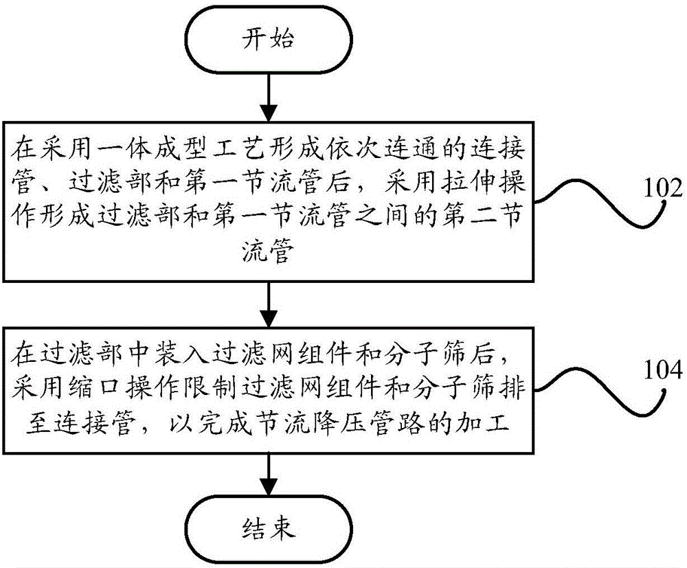
The invention provides a machining method of a throttling pressure-reducing pipeline, a throttling pressure-reducing device and a refrigerator. The machining method of the throttling pressure-reducing pipeline includes the steps that after a connecting pipe, a filtering portion and a first throttling pipe which communicate in sequence are formed through an integrated forming process, a second throttling pipe is formed between the filtering portion and the first throttling pipe through stretching operation; and after a filter net assembly and molecular sieves are put in the filtering portion, the filter net assembly and the molecular sieves are inhibited from being discharged to the connecting pipe through necking operation, and machining of the throttling pressure-reducing pipeline is finished. By means of the technical scheme, the machined and formed throttling pressure-reducing pipeline is of an integrated structure, the purpose of integrating filtering with throttling and pressure reducing is achieved, and therefore the service life of the throttling pressure-reducing pipeline is prolonged.

Description


Claims


Application Information

Patent Timeline
Owner HEFEI MIDEA REFRIGERATOR CO LTD
Learn More