a pipe joint

A technology of pipe joints and connecting parts, applied in the field of pipe joints, can solve the problems of liquid leakage, affect the progress of construction, increase the scrap rate, etc., and achieve the effects of accurate installation, increased utilization rate, and reduced scrap rate.

Active Publication Date: 2019-09-10
RENARD FLUID INTELLIGENCE TECH JIANGSU LTD BY SHARE LTD
View PDF8 Cites 0 Cited by
  • Summary
  • Abstract
  • Description
  • Claims
  • Application Information

AI Technical Summary

Problems solved by technology

Due to the long length of the ferrule, individual pipes will be stuck in a certain area of ​​the ferrule due to structural defects, and cannot completely enter the ferrule and ferrule. At this time, the operator often mistakenly believes that the pipe has been Installed in place to carry out the operation of squeezing the ferrule, so that waste products are generated, which increases the waste rate when the connecting pipe is connected with the pipe
Moreover, the collar only rests on the annular shoulder. If the collar moves with the ferrule and the tube during the extrusion process, it is also prone to waste.
The connection between the connecting pipe and the pipe is often carried out in the field construction, and the pipe is cut and intercepted on the spot. In the process of cutting and intercepting, burrs are often generated on the end face of the pipe, which makes the pipe easy to get stuck and cannot be completely In place, it is easy to produce waste products, once the waste products appear, it will affect the progress of the construction
And if no waste products are found, the firmness and sealing of the joints will be poor, and it is easy to cause liquid leakage during use.
[0005] The conventional technical means for the problem of pipe installation is to draw marking lines on the pipes, but the structural defects on the end faces of the pipes will lead to low accuracy of the length from the marking lines to the end faces of the pipes obtained by drawing the marking lines on site

Method used


Image

  • a pipe joint
  • a pipe joint
  • a pipe joint

Examples


Embodiment 1

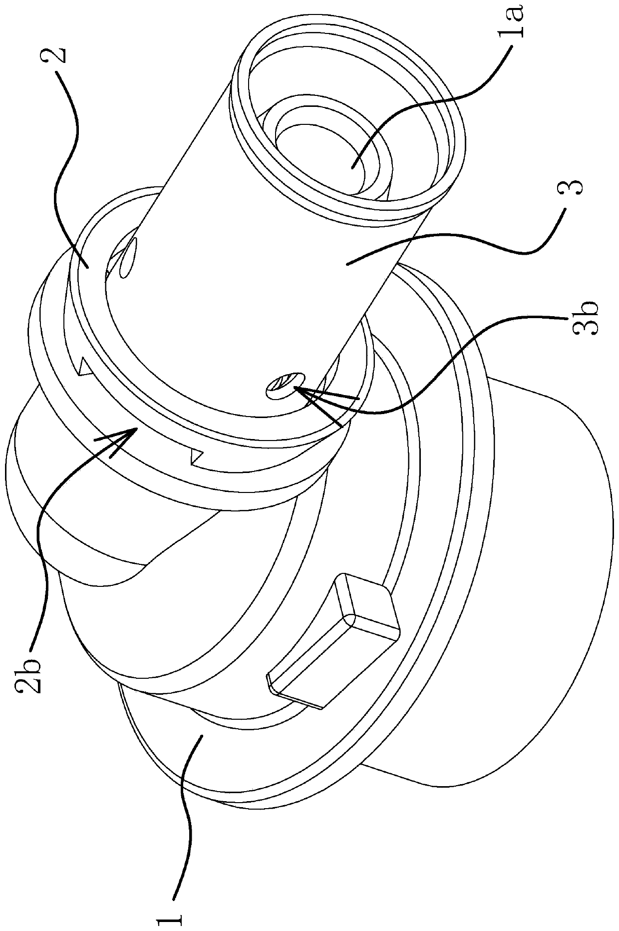
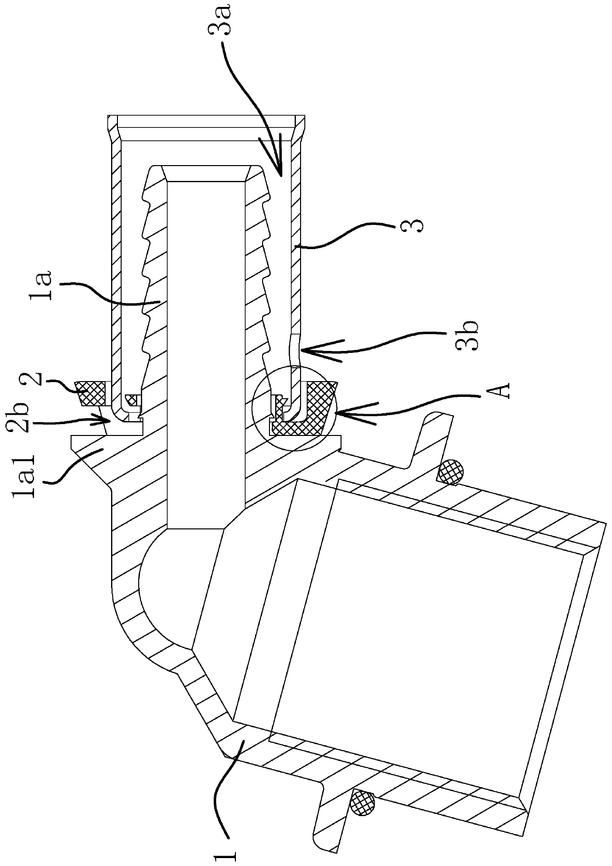
[0036] Such as Figure 1-Figure 6As shown, a pipe joint includes a joint body 1. The joint body 1 is generally made of hard materials such as copper or steel. The end of the joint body 1 has a connecting portion 1a for connecting with a pipe 4. The pipe 4 is generally plastic pipe. A protruding annular shoulder 1a1, an annular protruding ring 1a2 and a fixing part are sequentially provided on the outer surface of the connecting part 1a from the inner end to the outer end of the connecting part 1a, and the diameter of the outer surface of the protruding ring 1a2 is along the connecting part 1a. The direction from the inner end to the outer end gradually decreases, and the outer surface of the fixing part is wavy. The outer surface and the outer end surface of the connecting portion 1a are rounded, which facilitates the fitting of the tube 4 onto the connecting portion 1a. A collar 2 and a ferrule 3 are sheathed on the connecting portion 1a, and both the collar 2 and the ferru...


PUM


Abstract

The invention provides a pipe joint, belongs to the technical field of machinery, and solves the problem that a waste product is easily formed when the existing pipe joint and a pipe are connected. The pipe joint comprises a joint body, wherein a connecting part is arranged on the joint body; a cylindrical retainer ring and a cylindrical cutting sleeve are arranged on the connecting part in a sleeving manner; a groove is formed in the outer end face of the retainer ring; the inner end of the cutting sleeve is clamped in the groove; a mounting cavity is formed between the inner side face of the cutting sleeve and the outer side face of the connecting part; an observation hole I communicating with the bottom of the groove is formed in the outer side face of the retainer ring; an observation hole II communicating with the mounting cavity is formed in the outer side face of the inner end of the cutting sleeve; and the observation hole II is formed in the outer side of the outer end face of the retainer ring. The pipe joint has the advantages of low rejection rate during connection and the like.

Description

technical field [0001] The invention belongs to the technical field of machinery and relates to a pipe joint. Background technique [0002] When carrying out construction work on pipelines such as waterways, gas lines, and oil lines, it is necessary to connect two pipes through joints, and the connection method is generally threaded. However, threaded connections are more suitable for hard pipes and hard joints, but not for hoses and hard joints. [0003] The Chinese patent literature has proposed a pipe clamping structure [application number: 201320376887.5; authorized announcement number: CN20336450U], which includes a pipe and a connecting pipe. There is a connecting head at one end of the connecting pipe, and the pipe is sleeved on the connecting head and has a card on the periphery of the pipe. The connecting pipe is provided with a number of compression grooves located in the pipe and axially distributed. Between the compression grooves, there is a sealing structure b...

Claims


Application Information

Patent Timeline
Patent Type & Authority Patents(China)
IPC IPC(8): F16L21/08
Inventor 赵香荔
Owner RENARD FLUID INTELLIGENCE TECH JIANGSU LTD BY SHARE LTD
Why Eureka
Try Eureka