
Filter for casting and filtering system comprising same

A filtering system and filter technology, applied in casting molding equipment, molds, mold components, etc., can solve the problems of increasing the horizontal projection area of ​​the gating system, increasing the sand intake of the gating system, and a single structure of the filtering system, and reducing the The effect of sand intake, increased sand intake, and flexible structure

Active Publication Date: 2017-05-17
NINGXIA KOCEL MOLD
View PDF9 Cites 0 Cited by
  • Summary
  • Abstract
  • Description
  • Claims
  • Application Information

AI Technical Summary

Problems solved by technology

In order to improve the filtering effect, the filter screen is generally designed near the inlet of the mold cavity. For the traditional casting process, due to the restriction of the mold draft angle and the material withdrawal method, the optional filter system has a single structure and a simple process flow. Long, consumes a lot of molten iron
In order to achieve the function of filtering impurities in molten iron, the cross-sectional area of ​​the filtration system is larger than that of other parts of the gating system. Therefore, the filtration system will increase the horizontal projected area of ​​the gating system, thereby increasing the amount of sand eaten above the gating system and increasing the cost.

Method used


Image

  • Filter for casting and filtering system comprising same
  • Filter for casting and filtering system comprising same
  • Filter for casting and filtering system comprising same

Examples


Embodiment 1

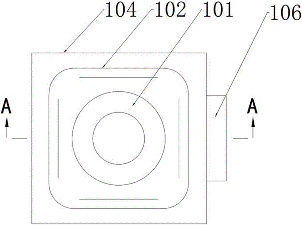
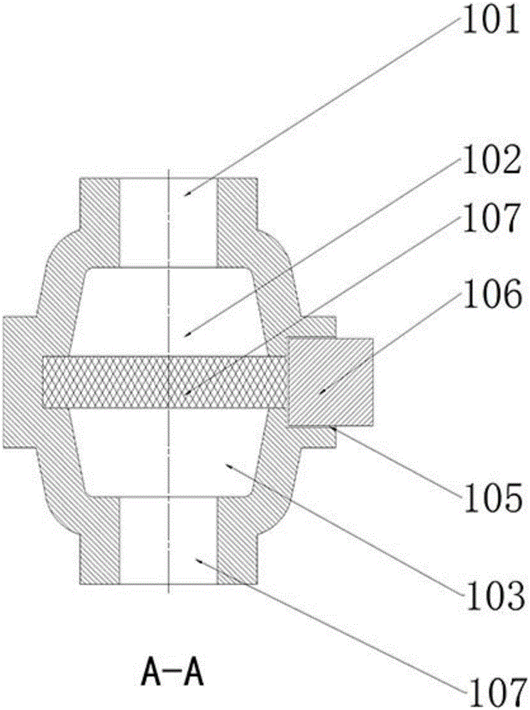
[0044] figure 1 The shown single filter has a structure including: an inlet (101) arranged on the top of the filter for introducing molten iron into the filter and connecting to the runner in the gating system; The upper liquid storage area (102) and the lower liquid storage area (103) are arranged below the port (101) and are mirrored along the horizontal axis to reduce the flow rate of molten iron and enlarge the contact area between molten iron and the filter screen; The middle of the liquid area (102) and the lower liquid storage area (103), the cross section is a rectangle, the boundary size is larger than the cross-sectional size of the liquid storage area, and is used to carry the filter screen tank (104); The side surface in the width direction of the filter mesh slot (104), the longitudinal section size is larger than the longitudinal section size of the filter mesh slot (104), the window (105) for inserting the filter mesh into the filter mesh slot (104), and the win...

Embodiment 2

[0047] figure 2The shown in-line filtration system has a structure including: a main inlet (201) arranged at the top for introducing molten iron into the filtration system and connecting to the sprue of the gating system; 201) below, extending distribution to reduce the flow rate of molten iron and distributing molten iron to each filter (100) deceleration flow channel (202), there is only one deceleration flow channel (202), horizontally extending distribution; arranged in the main inlet The flow port (201) is directly below the first end of the deceleration flow channel, and is located below the deceleration flow channel (202), for reducing the flow rate of molten iron and collecting the first strand of iron charged into the filter system A buffer pocket (203) for liquid; four filters (100) arranged in parallel under the deceleration flow channel (202); located at the second end of the deceleration flow channel (202), used to clean the loose sand in the filter system a mai...

Embodiment 3

[0050] image 3 The shown rotary filtration system has a structure including: a main inlet (201) arranged at the top for introducing molten iron into the filtration system and connected to the sprue of the gating system; Below 201), there are deceleration flow channels (202) for reducing the flow rate of molten iron and distributing molten iron to each filter (100). The inner circumferential array is distributed; it is arranged directly below the main inlet (201), communicates with the first end of the deceleration flow channel, and is located below the deceleration flow channel (202), so as to reduce the flow rate of molten iron and a buffer socket (203) for collecting the first strand of molten iron charged into the filtration system; a filter (100) is connected below each deceleration flow channel (202); hanging handles (206) symmetrically distributed on both sides of the end .

[0051] This rotary filter system is usually used in the production of rotary castings with ce...


PUM


Abstract

The invention provides a filter for casing. The filter comprises a flow inlet, an upper liquid storing area, a lower liquid storing area, a filter screen groove, a window, a sticky core and a flow outlet, wherein the flow inlet is formed in the top of the filter and used for guiding molten iron into the filter; the upper liquid storing area and the lower liquid storing area are arranged below the flow inlet and used for reducing flow speed of iron liquid and enlarging the contact area between the molten iron and a filter screen, the filter screen groove is formed between the upper liquid storing area and the lower liquid storing area, the cross section of the filter screen groove is rectangular, the boundary size of the filter screen groove is larger than the section size of the liquid storing areas, the filter screen groove is used for bearing a filter screen, the window is arranged on the side face of the width direction of the filter screen groove, and used for inserting the filter screen into the filter screen groove, the sticky core is installed on the window in a clearance fit manner, the flow outlet is formed in the lower portion of the lower liquid storing area, the flow outlet and the flow inlet are distributed symmetrically with the filter screen groove as an axis, and the flow outlet is used for connecting flow input points of a casting cavity. A filtering system utilizes the multiple filters to be combined in many forms to be suitable for producing castings of different structure shapes and various weights.

Description

technical field [0001] The present invention relates to the technical field of casting, and more particularly, to a filtering system for casting molds. Background technique [0002] In the casting production process, in order to improve the quality of the molten iron entering the mold cavity, a filter screen is often used in the design of the casting process. The filter screen is placed in the filter system. In order to improve the filtering effect, the filter screen is generally designed close to the inlet of the mold cavity. For the traditional casting process, due to the constraints of the mold draft angle and the material withdrawal method, the filter system that can be selected has a single structure and a process flow. long and consumes a large amount of molten iron. In order to filter impurities in molten iron, the filter system has a larger cross-sectional area than other parts of the gating system. Therefore, the filter system will increase the horizontal projecti...

Claims


Application Information

Patent Timeline
IPC IPC(8): B22C9/08
CPCB22C9/086
Inventor 杜文强苗润青
Owner NINGXIA KOCEL MOLD
Learn More