Wireless indoor fan coil control system

An indoor fan and control system technology, applied in general control systems, control/regulation systems, computer control, etc., can solve the problems of measurement error, unsuitable for precision measurement circuits, large 3.3V voltage ripple, etc., to reduce power ripple wave, solving construction difficulties, and the effect of low own noise

Pending Publication Date: 2017-05-10
山东金洲科瑞节能科技有限公司
View PDF6 Cites 2 Cited by
  • Summary
  • Abstract
  • Description
  • Claims
  • Application Information

AI Technical Summary

Problems solved by technology

Although this makes the structure relatively simple, the 3.3V voltage ripple obtained is relatively large, which is easy to cause measurement errors, and is not suitable for precision measurement circuits.

Method used


Image

  • Wireless indoor fan coil control system
  • Wireless indoor fan coil control system
  • Wireless indoor fan coil control system

Examples


Embodiment Construction

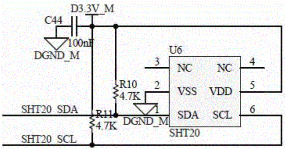
[0028] Such as figure 1 As shown, a wireless indoor fan coil control system includes a microprocessor control circuit, an indoor temperature acquisition circuit, a wireless communication circuit, a coil fan control circuit, a power supply circuit, a human-computer interaction module, and an output terminal of the indoor temperature acquisition circuit It is connected with the temperature data input end of the microprocessor control circuit, the fan signal input end of the microprocessor control circuit is connected with the data transceiver end of the wireless communication circuit, and the remote data transceiver end of the wireless communication circuit is wirelessly connected with the host computer; the microprocessor The coil fan data input end of the control circuit is connected with the output end of the coil fan control circuit; the power supply circuit and the man-machine interaction module are respectively connected with the microprocessor control circuit.

[0029] Su...


PUM


Abstract

The invention discloses a wireless indoor fan coil control system comprising a microprocessor control circuit, an indoor temperature acquisition circuit, a wireless communication circuit, a coil fan control circuit, a power supply circuit and a man-machine interaction module; the indoor temperature acquisition circuit output end is connected with a temperature data input end of the microprocessor control circuit; a fan signal input end of the microprocessor control circuit is connected with a data transceiver end of the wireless communication circuit; a remote data transceiver end of the wireless communication circuit is wireless connected with a host; the coil fan data input end of the microprocessor control circuit is connected with the output end of the coil fan control circuit; the power supply circuit and the man-machine interaction module are respectively connected with the microprocessor control circuit.

Description

technical field [0001] The invention relates to a wireless indoor fan coil control system. Background technique [0002] The wireless indoor fan coil control system adjusts the indoor temperature by controlling the air flow of the indoor fan coil. Traditional indoor fan coil control devices mostly use RS485 bus control, which requires the laying of a large number of communication lines, which increases construction difficulty and maintenance costs. The 3.3V power supply used in the control system generally adopts 220V transformer rectification and filtering to obtain 12V DC voltage. After obtaining DC 12V, DC-DC power supply chips are generally used to directly cool down the voltage to 3.3V voltage. Although this makes the structure relatively simple, the resulting 3.3V voltage ripple is relatively large, which is likely to cause measurement errors and is not suitable for precision measurement circuits. Contents of the invention [0003] The purpose of the present invent...

Claims


Application Information

Patent Timeline
Patent Type & Authority Applications(China)
IPC IPC(8): G05B19/042
CPCG05B19/0423G05B2219/21014
Inventor 董嵩华
Owner 山东金洲科瑞节能科技有限公司
Why Eureka
Try Eureka