
Plug connector and casing assembly thereof

A technology of plug connector and housing assembly, which is applied in the field of plug connector and its housing assembly, and can solve the problems of unfavorable sub-board plug insulator and outer shell, locking shell and outer shell relative floating, difficult installation, and sliding friction Large force and other problems, to achieve the effect of reducing processing cost, low processing accuracy requirements, and reducing area

Active Publication Date: 2017-05-10
CHINA AVIATION OPTICAL-ELECTRICAL TECH CO LTD
View PDF5 Cites 8 Cited by
  • Summary
  • Abstract
  • Description
  • Claims
  • Application Information

AI Technical Summary

Problems solved by technology

The plug outer shell, the insulator and the locking shell of the sub-board plug are all inserted together through the inner and outer peripheral surfaces, and the gap between the inner peripheral surface of the mounting hole of the outer shell and the outer peripheral surface of the locking shell and The gap between the inner peripheral surface of the mounting hole of the locking housing and the outer peripheral surface of the insulator is relatively small. During the installation process, the relative sliding friction force will be large, and it is very difficult to install. At the same time, due to the relatively large sliding friction force during the insertion process, it will also affect the relative floating between the outer shell, the locking shell and the insulator. It is not conducive to the relative floating between the daughter board plug insulator and the outer shell and the locking shell and the outer shell

Method used


Image

  • Plug connector and casing assembly thereof
  • Plug connector and casing assembly thereof
  • Plug connector and casing assembly thereof

Examples


Embodiment Construction

[0032] Embodiments of the present invention will be further described below in conjunction with the accompanying drawings.

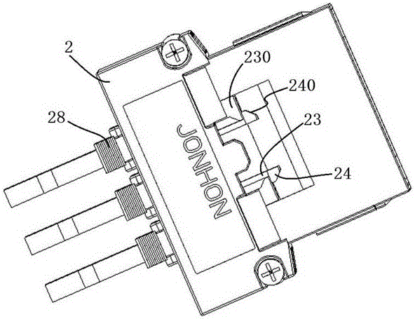
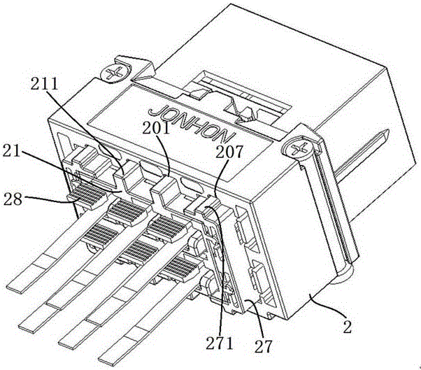
[0033] Specific embodiments of the plug connector of the present invention, such as figure 1 As shown, the plug connector of the present invention is a daughter board plug, and the plug connector of the present invention is described by taking the daughter board plug as an example. Of course, in other embodiments, the plug connector may not be a daughter board plug, but may be other plug connector.

[0034] The sub-board plug is installed on the sub-board 20 during use, and is used for plugging and mating with the backplane socket 1 installed on the backplane 10 to realize optical signal transmission between the backplane and the sub-board. Of course, in other implementation manners, the plug of the sub-board may also be a conductive plug, which is used to realize the transfer and transmission of electrical signals.

[0035] For the sake of clarity, th...


PUM


Abstract

The invention provides a plug connector and a casing assembly thereof. The plug connector comprises a casing assembly, the casing assembly comprises an outer casing and a casing part which is inserted into the outer casing in the back and forth direction, the interior of the outer casing is provided with an anti-drop stopping structure which is used for stopping the casing part in the back and forth direction in order to prevent the casing part from dropping from the outer casing, the interior of the casing part is provided with a plug contact, and the casing part and the outer casing achieve positioning and plug-in mounting through a casing key-groove mating structure extending in front-back direction. With respect to the plug connector, the casing part and the outer casing achieve positioning and plug-in mounting through the key-groove mating structure, during the plug-in mounting process, the mating area of the mounting surface is reduced, the precision demand on the mounting surface is reduced, and the relative sliding friction force generated in the plug-in mounting process is also reduced.

Description

technical field [0001] The invention relates to a plug connector and its shell assembly. Background technique [0002] The circuit printed board is an important electronic component in the communication equipment cabinet, which is divided into a vertically placed backplane and a horizontally placed subboard. During the operation of the device, the communication data needs to be transmitted between the backplane and the daughterboard. In the traditional way, most optical jumpers are used to realize the intermediate transfer between the backplane and the sub-board, but a large number of optical jumpers occupy space, the wiring is messy, and the later maintenance is very inconvenient. [0003] In response to such problems, inter-board optical fiber connectors emerged as the times require. For example, the Chinese invention patent with the application number CN201610303576.4 and the application date of 2016.5.10 discloses an inter-board connector assembly and its sub-board plu...

Claims


Application Information

Patent Timeline
IPC IPC(8): G02B6/42
CPCG02B6/4261
Inventor 周生贺余永强徐耕
Owner CHINA AVIATION OPTICAL-ELECTRICAL TECH CO LTD
Learn More