Two-dimensional season cracking model considering bending moment contribution factor

A bending moment and aging technology, applied in special data processing applications, instruments, electrical digital data processing, etc., can solve problems such as failure to reflect shear fracture strength, inconformity of movement mode, and exaggerated bond torque damage to rock mass.

Active Publication Date: 2017-05-10
CHANGJIANG RIVER SCI RES INST CHANGJIANG WATER RESOURCES COMMISSION
View PDF2 Cites 2 Cited by
  • Summary
  • Abstract
  • Description
  • Claims
  • Application Information

AI Technical Summary

Problems solved by technology

However, this type of parallel bonding model has many shortcomings: First, after the parallel bonding fractures, only the sliding friction force is considered between the particles, and the contact mode between the fractured particles is not considered, which does not conform to the different mesoscopic properties of the rock mass after fracture. The movement mode of the particles under the external load; secondly, the shear fracture criterion between particles is a horizontal line parallel to the normal stress of the parallel bond, that is, the shear rupture criterion has nothing to do with the normal stress state of the parallel bond, as long as the parallel bond If the bond shear stress is greater than or equal to the fixed parallel bond shear fracture strength, shear fracture can occur between particles, which cannot reflect the objective fact that different parallel bond normal stresses in the rock mass have different parallel bond shear fracture strengths; in addition , for friction-bonding materials such as rock mass, the above-mentioned parallel bonding model does not consider the influence of the difference in bonding torque on contact failure, and the contribution of bonding torque to different lithologies is regarded as Consistent, exaggerating the destructive effect of bonding moment on rock mass

Method used


Image

  • Two-dimensional season cracking model considering bending moment contribution factor
  • Two-dimensional season cracking model considering bending moment contribution factor
  • Two-dimensional season cracking model considering bending moment contribution factor

Examples


Embodiment Construction

[0041] The model of the present invention will be described in detail below in conjunction with the accompanying drawings, specific construction steps and implementation examples. The illustrations of the examples are only for assisting the understanding of the present invention, and do not limit the practical application scope of the present invention. After reading the present invention, modifications to various equivalent forms of the present invention by those skilled in the art belong to the scope defined by the claims of the present invention.

[0042] Note: All the labels in the manual are preceded by formulas, such as formula (1), which are all formula labels.

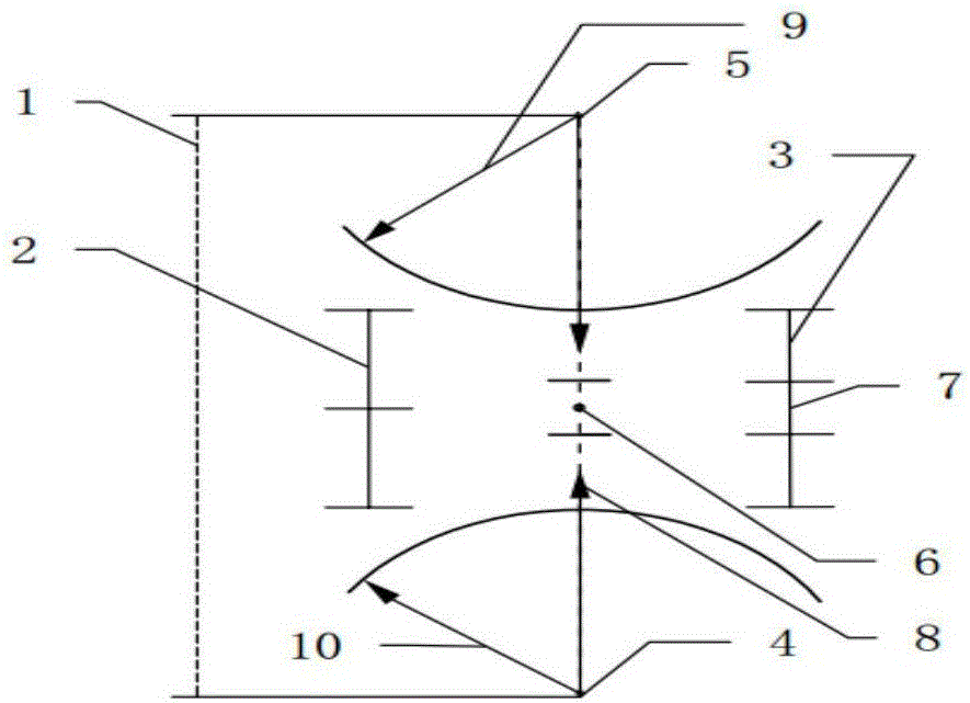
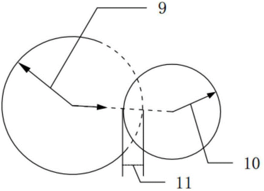
[0043] Such as Figure 1 to Figure 11 As shown, the two-dimensional aging cracking model considering the bending moment contribution factor of the present invention is suitable for the two-dimensional particle discrete element, the two-dimensional particle discontinuous deformation analysis method, and the two...


PUM

PropertyMeasurementUnit
diameteraaaaaaaaaa
heightaaaaaaaaaa

Abstract

The invention discloses a two-dimensional season cracking model considering a bending moment contribution factor. The two-dimensional season cracking model comprises a rock meso-level particle parallel bond stress two-dimensional mode considering the bending moment contribution factor, a meso-level particle parallel bond season cracking deterioration attenuation two-dimensional exponential mode considering the bending moment contribution factor, a Mohr-Coulomb meso-level particle parallel bond season cracking criterion considering the bending moment contribution effect and with a tensile cut-off limit, and a meso-level particle linear contact two-dimensional model considering a damping effect. The season cracking model disclosed by the invention is applicable to two-dimensional granular discrete elements, two-dimensional granular discontinuous deformation analysis methods and two-dimensional granular manifold methods, and is capable of providing a technical support for long-term stability prediction, evaluation and optimization design of surrounding rock in deep rock mass engineering in a planar state.

Description

technical field [0001] The invention relates to the technical field of engineering rock mass mesoscopic aging crack analysis, in particular to a two-dimensional aging cracking model considering the contribution factor of bending moment. Background technique [0002] Instability and destruction of deep rock mass engineering after excavation often do not occur immediately after excavation. Generally, there are obvious deformation and rupture timeliness and hysteresis of catastrophe (rockburst, large deformation, etc.), which seriously endanger the safety of the project. Construction safety and long-term operation. At present, there are relatively few research results on time-efficiency mechanics in the mesoscopic aspect. Liu Ning and others conducted experiments and numerical analyzes on the time effect of Jinping marble fracture (Particle flow simulation of the time effect of deep-buried marble fracture expansion, Journal of Rock Mechanics and Engineering, 2011, Vol.30No.10:...

Claims


Application Information

Patent Timeline
Patent Type & Authority Applications(China)
IPC IPC(8): G01N33/24G06F17/50
CPCG01N33/24G06F30/367
Inventor 黄书岭丁秀丽李欢邬爱清徐平张雨霆高源朱良韬
Owner CHANGJIANG RIVER SCI RES INST CHANGJIANG WATER RESOURCES COMMISSION
Why Eureka
Try Eureka